CSI-RS configuration method and method, base station and terminal for measuring channel

A configuration method and base station technology, applied in the field of communication, can solve problems such as subframe and paging collisions, pseudo-collisions, etc.

Inactive Publication Date: 2013-11-13
ZTE CORP
View PDF5 Cites 22 Cited by
  • Summary
  • Abstract
  • Description
  • Claims
  • Application Information

AI Technical Summary

Problems solved by technology

[0006] The technical problem to be solved by the present invention is to provide a CSI-RS configuration method, a channel measurement met

Method used


Image

  • CSI-RS configuration method and method, base station and terminal for measuring channel
  • CSI-RS configuration method and method, base station and terminal for measuring channel
  • CSI-RS configuration method and method, base station and terminal for measuring channel

Examples


Embodiment 1

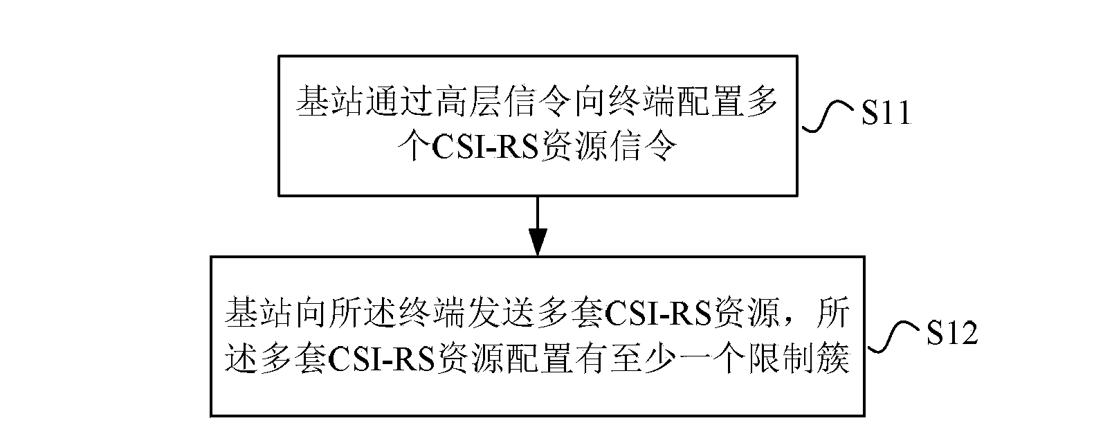
[0131] Assuming that UE1 is a user of R11 or later, the base station side configures multiple CSI-RS resource signaling and multiple sets of CSI-RS resources to the terminal through high-layer signaling.

[0132] The multiple sets of CSI-RS resources may be multiple sets of non-zero-power CSI-RS resources, or multiple sets of zero-power CSI-RS resources, or multiple sets of non-zero-power CSI-RS resources and a set of zero-power CSI-RS resources. The RS resources may also be multiple sets of non-zero-power CSI-RS resources and multiple sets of zero-power CSI-RS resources.

[0133] The base station may instruct UE1 to use interference measurement resources or rate matching resources by configuring one or more sets of zero-power CSI-RS resources.

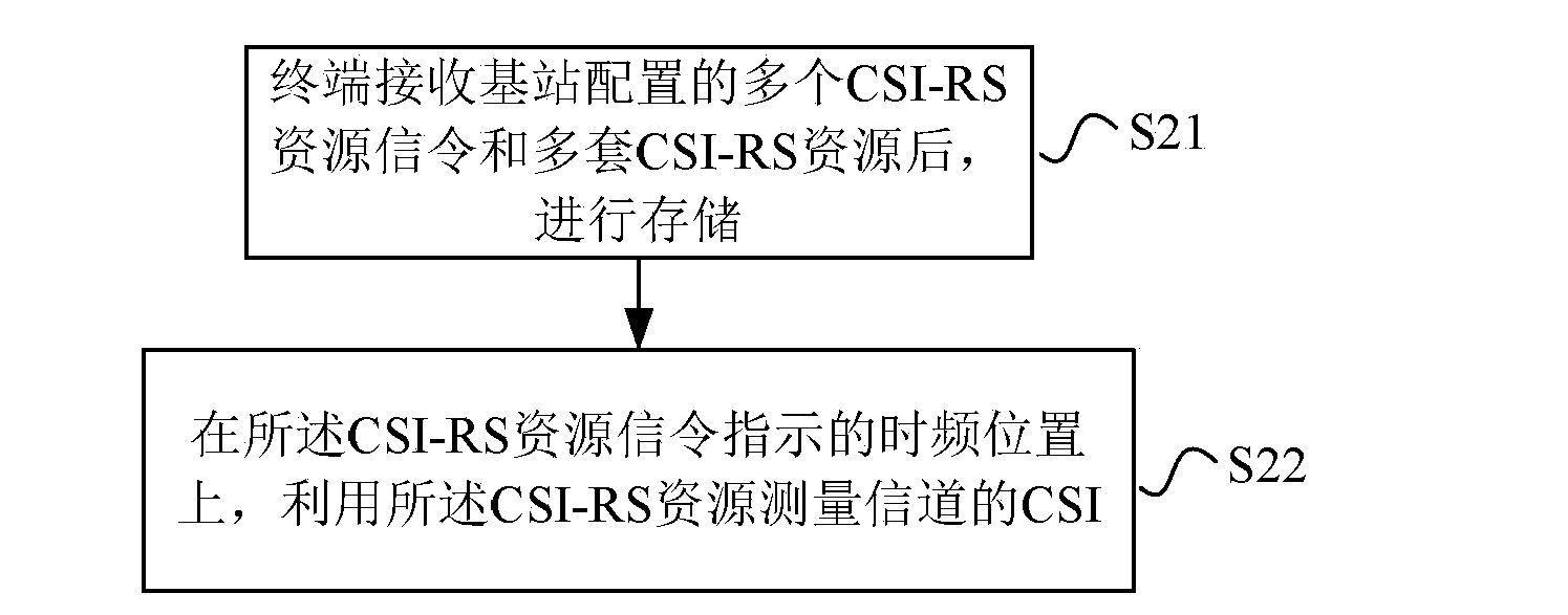
[0134] After receiving multiple CSI-RS resource signaling and multiple sets of CSI-RS resources configured by the base station, UE1 stores them. UE1 uses the CSI-RS resource to measure the CSI of the channel at the time-frequency pos...

Embodiment 2

[0196] The difference between this embodiment and Embodiment 1 is that the base station side configures a unified CSI-RS reception restriction cluster for multiple sets of configured non-zero-power CSI-RS resources, and configures a unified CSI-RS reception restriction cluster for one or more configured sets of zero-power CSI-RS resources. A unified CSI-RS receives restricted clusters. The two sets of CSI-RS reception restriction clusters may adopt different CSI-RS restriction cluster configuration methods.

Embodiment 3

[0198] The difference between this embodiment and Embodiment 1 is that the base station side independently configures CSI-RS reception restriction clusters for multiple sets of configured non-zero-power CSI-RS resources, and configures one or more sets of zero-power CSI-RS resources. A unified CSI-RS receives restricted clusters.

[0199] The non-zero-power CSI-RS reception restriction cluster may adopt a CSI-RS restriction cluster configuration method different from that of the zero-power CSI-RS restriction cluster.

[0200] The zero-power CSI-RS reception restriction cluster may default to the union of all non-zero-power CSI-RS resource reception restriction clusters.

[0201] The zero-power CSI-RS reception restriction cluster may default to a union of some non-zero-power CSI-RS resource reception restriction clusters.

[0202] The zero-power CSI-RS reception restriction cluster may be a union of some or all of the non-zero-power CSI-RS resource reception restriction clust...


PUM


Abstract

The invention provides a CSI-RS configuration method and a method, a base station and a terminal for measuring a channel. The method comprises the steps that the base station configures a plurality of CSI-RSs for the terminal through high-level signaling; the base station sends multiple sets of CSI-RS resources to the terminal, the multiple sets of CSI-RS resources are configured with at least one limiting cluster, and the limiting cluster is used for indicating that a terminal side cannot receive radio frames and / or subframes of the CSI-RSs. Accordingly, collision problems or untrue collision problems between the CSI-RS subframes and Paging can be resolved.

Description

technical field [0001] The invention relates to the communication field, in particular to a channel state information reference signal configuration method, a channel measurement method, a base station and a terminal. Background technique [0002] After the Long Term Evolution (LTE for short) system has gone through several versions of R8 / 9 / 10, the R11 technology has been accurately studied successively. At present, some R8 products are gradually commercialized, and R9 and R10 are subject to further product planning. [0003] After going through the stages of R8 and R9, R10 added many new features on the basis of the first two, for example, DMRS (Demodulation Reference Signal, demodulation reference signal), CSI-RS (Channel State Information Reference Signal, channel state Information reference signal) and other pilot characteristics, 8-antenna support and other transmission and feedback characteristics, etc., especially eICIC (ehanced Inter-Cell Interference Cancellin, enh...

Claims


Application Information

Patent Timeline
IPC IPC(8): H04L1/00H04W72/04H04W88/02H04W88/08H04W24/00
Inventor 郭森宝李儒岳孙云锋张峻峰
Owner ZTE CORP
Why Eureka
Try Eureka