Electrode terminal

An electrode lead-out terminal and electrode lead-out technology, which is applied in the direction of electric heating devices, electrical components, heating through discharge, etc., can solve the problems of electrode lead-out and sealing without a good solution, so as to increase the contact area and improve the contact area. , Good effect of large area transmission

Inactive Publication Date: 2015-08-05
曲颜发
View PDF6 Cites 0 Cited by
  • Summary
  • Abstract
  • Description
  • Claims
  • Application Information

AI Technical Summary

Problems solved by technology

[0002] The electrode leads in heat treatment equipment have strict requirements on sealing. During heat treatment, external cold air is not allowed to enter the heat treatment area (inside the heating furnace). In this field, there has been no good solution for electrode lead-out and sealing.

Method used


Image

  • Electrode terminal
  • Electrode terminal

Examples


Embodiment 1

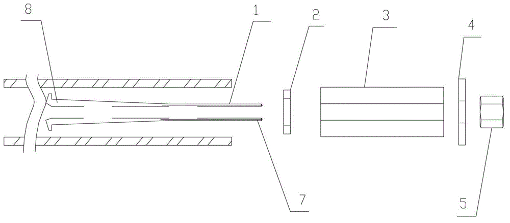
[0014] An embodiment of the present invention provides an electrode lead-out terminal, including: an electrode lead-out shell, a hollow expansion bolt, a first annular gasket, a second annular gasket, an annular expansion body, a nut, and a wire;

[0015] The expansion bolt passes through the first annular gasket, the annular expansion body, the second annular gasket, and the nut in turn, and is threadedly connected with the nut; the wire passes through the expansion bolt ;

[0016] The expansion end of the expansion bolt is inside the electrode lead-out casing, and the end of the expansion bolt connected to the nut is outside the electrode lead-out casing;

[0017] The expansion end is provided with an extension edge, and in the direction from the expansion end to the end of the expansion bolt connected to the nut, the extension edge, the first annular gasket, the annular expansion body, the first The two ring gaskets and the nuts are in close contact with each other in turn...

Embodiment 2

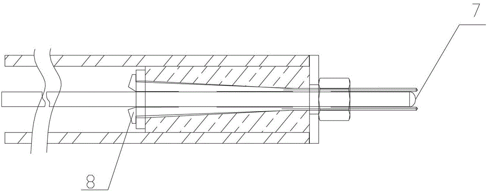
[0021] An electrode lead-out terminal, such as figure 1 , 2 As shown: including the electrode lead-out casing, a hollow expansion bolt 1 is provided inside the electrode lead-out casing. The expansion bolt 1 is made of copper, iron, or stainless steel. One end of the expansion bolt 1 is an expansion end 8. The expansion end 8 presents a multi-lobe structure, which can be understood as splitting the expansion bolt 1 into multiple lobes in the axial direction. All the lobes can be tightly entangled or there may be gaps between adjacent lobes, depending on the expansion bolt 1 inserted into the hollow. The thickness of the wire. The other end 7 of the expansion bolt 1 is provided with threads, through which the expansion bolt 1 is connected with the nut 5 and is located outside the electrode lead-out casing. The expansion end 8 of the expansion bolt 1 is provided with an extension edge. Due to the extension edge, the expansion end 8 is trumpet-shaped. In the direction from the ...


PUM


Abstract

The invention relates to the thermoelectricity field, in particular to an electrode leading-out terminal. The electrode leading-out terminal comprises an electrode leading-out casing, a hollow expansion bolt, a first annular spacer, a second annular spacer, an annular expansion body, a nut and a lead wire. The expansion bolt sequentially penetrates the first annular spacer, the annular expansion body, the second annular spacer and the nut and is in threaded connection with the nut. The lead wire penetrates the expansion bolt. The expansion end of the expansion bolt is located inside the electrode leading-out casing, and one end of the expansion bolt connected with the nut is located outside the electrode leading-out casing. The expansion end is provided with the outer extending edge, and the outer extending edge, the first annular spacer, the annular expansion body, the second annular spacer and the nut are sequentially and tightly in contact in the direction from the expansion end to one end of the expansion bolt connected with the nut. The second annular spacer is in tight contact with the end face of the electrode leading-out casing. The electrode leading-out terminal can prevent assemblies from sliding through large thrust face and achieve the airtight effect.

Description

technical field [0001] The invention relates to the field of thermoelectricity, in particular to an electrode lead-out terminal. Background technique [0002] The electrode leads in heat treatment equipment have strict requirements on sealing. During heat treatment, external cold air is not allowed to enter the heat treatment area (inside the heating furnace). In this field, there has been no good solution for electrode lead-out and sealing. Contents of the invention [0003] The object of the present invention is to provide an electrode lead-out terminal to solve the above-mentioned problems. [0004] An embodiment of the present invention provides an electrode lead-out terminal, including: an electrode lead-out shell, a hollow expansion bolt, a first annular gasket, a second annular gasket, an annular expansion body, a nut, and a wire; [0005] The expansion bolt passes through the first annular gasket, the annular expansion body, the second annular gasket, and the nut ...

Claims


Application Information

Patent Timeline
Patent Type & Authority Patents(China)
IPC IPC(8): H05B7/101H05B7/103
Inventor 曲颜发
Owner 曲颜发
Why Eureka
Try Eureka