Cutting apparatus

A support surface and fixed blade technology, which is applied in the cutting of textile materials, textiles and papermaking, metal processing, etc., can solve the problems of cloth 106 damage, fixed blade 104 damage, sharpness reduction cloth, etc.

Active Publication Date: 2013-11-13
那姆克斯有限公司
View PDF4 Cites 3 Cited by
  • Summary
  • Abstract
  • Description
  • Claims
  • Application Information

AI Technical Summary

Problems solved by technology

[0009] However, the cutting device of Patent Document 1 may cause the fixed blade 104 to receive excessive resistance from the cloth 106 due to a reduction in the sharpness of the rotating blade 102 or the fixed blade 104 or wrinkles in the cloth, thereby jamming the cutting device. hang on fabric 106
When the fixed blade 104 is caught on the cloth 106, it may cause the cloth 106 to move along the driving direction of the cutter head, so that the cutting operation may be interrupted, or the cloth 106 may be damaged.
In addition, since the driving force of the cutter head acts directly in the state where the fixed blade 104 is caught on the cloth 106, the fixed blade 104 may be damaged.

Method used


Image

  • Cutting apparatus
  • Cutting apparatus
  • Cutting apparatus

Examples


Embodiment Construction

[0053] Hereinafter, embodiments of the present invention will be described in detail with reference to the attached drawings.

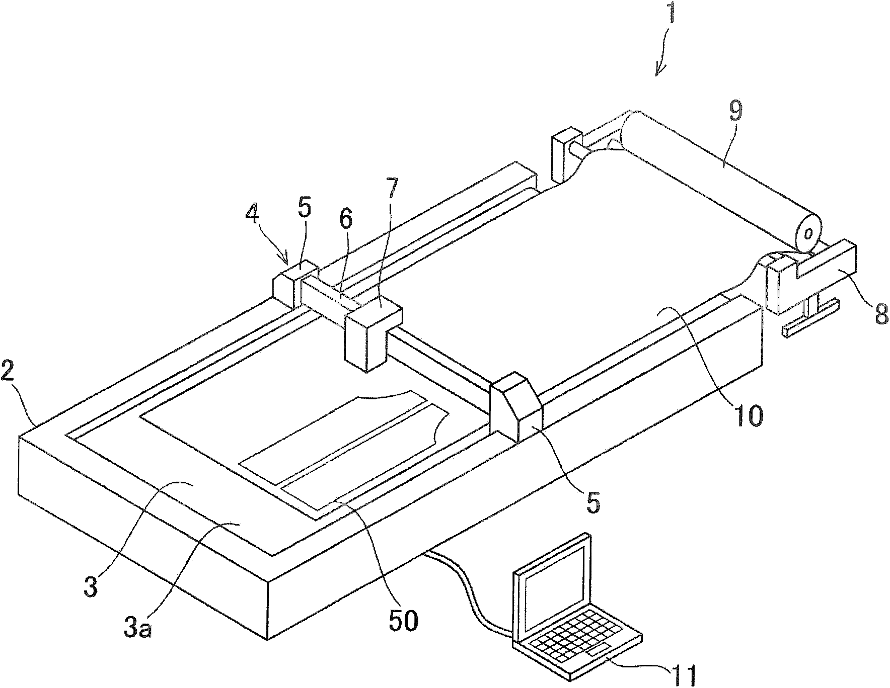
[0054] The cutting device according to the embodiment of the present invention is a plotter-type cutting device that cuts cloth as a sheet to create a pattern piece for clothing. The cutting device 1 such as figure 1 As shown, it roughly consists of a cutting table 2, a cutter unit 4, a fabric spreader 8, and a control device 11 as a control unit and a rotary blade control unit.

[0055] The cutting table 2 has a built-in belt conveyor that conveys the cloth 10 from the cloth opener 8 and supports the cloth 10 during cutting. The belt conveyor mechanism is built in both ends of the cutting table 2 in the longitudinal direction, and the conveyor belt 3 as a support portion is spanned between unillustrated pulleys extending in the lateral direction. The upper surface of the conveyor belt 3 constituting the belt conveyor is exposed on the upper side o...


PUM


Abstract

Provided is a cutting apparatus (1), which can prevent a sheet material (10) from moving and being damaged even if a fixed blade (43) receives a resistive force from the sheet material, and which can prevent the fixed blade from being damaged. A cutter unit (4) of a cutting apparatus is configured of a pair of carriages (5) that travel along rails in the longitudinal direction of a cutting table (2), and a cutter head (7), which travels along a rail provided on a beam member (6) between the carriages. The cutter head has a rotating blade (29) and a fixed blade that is pressed to the blade edge of the rotating blade. The fixed blade is held by means of a fixed blade holder (42), which is pivotally supported to the leading edge portion of a blade spring (40) such that the blade holder can swing, and the fixed blade is held at a cutting position by attracting the fixed blade holder using a permanent magnet (44). When the fixed blade receives an excessive resistive force from a fabric (10), the fixed blade inverts and retracts in the direction opposite to the drive direction of the cutter head.

Description

technical field [0001] The present invention relates to a cutting device for cutting a sheet such as cloth along a cutting pattern. Background technique [0002] Conventionally, there has been a plotter-type cutting device as a cutting device for cutting cloth for clothing to produce pattern sheets. The plotter-type cutting device has: a cutting workbench with a supporting surface for supporting the cloth; a pair of carriages that move along two rails extending on the edge of the cutting workbench in the longitudinal direction; A beam member between a pair of carriages; a cutter head mounted on the beam member and moving along a track. The cutting device inputs cutting data indicating a cutting pattern of the design sheet to the control unit, and based on the cutting data, drives the cutter built in the cutter head along the planar direction while operating the cutter to cut the cloth, thereby producing the design sheet. [0003] As such a cutting device, there is known a ...

Claims


Application Information

Patent Timeline
Patent Type & Authority Applications(China)
IPC IPC(8): B26D7/22B26D5/00D06H7/00
CPCB26D7/22B26D1/185B26D7/01D06H7/00B26D1/225B26D7/015B26F1/3813B26D1/045
Inventor 那须信夫
Owner 那姆克斯有限公司
Why Eureka
Try Eureka