
Multi-wire cutting machine guide wheel wire groove and its processing method

A multi-wire cutting machine and guide wheel technology, applied in stone processing equipment, working accessories, manufacturing tools, etc., can solve the impact of the overall slicing quality of crystal slices, the surface grooves, line marks or steps on the wafer surface, which affect the quality of crystal rod slicing and other problems, to achieve the effect of reducing the axial width, reducing line marks, and avoiding "jumping lines"

Active Publication Date: 2016-03-09
GCL POLY ENERGY HLDG
View PDF8 Cites 0 Cited by
  • Summary
  • Abstract
  • Description
  • Claims
  • Application Information

AI Technical Summary

Problems solved by technology

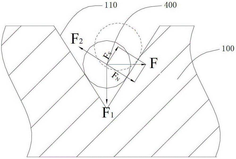
Once the cutting wire 400 moves axially on the cutting path, it will inevitably cause defects such as grooves, line marks or steps on the wafer surface on the cutting path, thereby affecting the quality of the crystal rod section
Additionally, in the above F S Under the action of component force, the cutting steel wire 400 is easy to move to the top of the groove and break away from the wire groove 110, resulting in the accident of "jumping wire" of the cutting wire, which affects the overall slicing quality of crystal slices

Method used

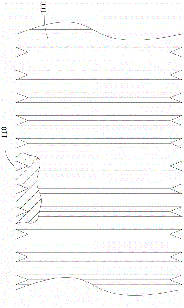

Image

  • Multi-wire cutting machine guide wheel wire groove and its processing method
  • Multi-wire cutting machine guide wheel wire groove and its processing method
  • Multi-wire cutting machine guide wheel wire groove and its processing method

Examples


Embodiment approach 1

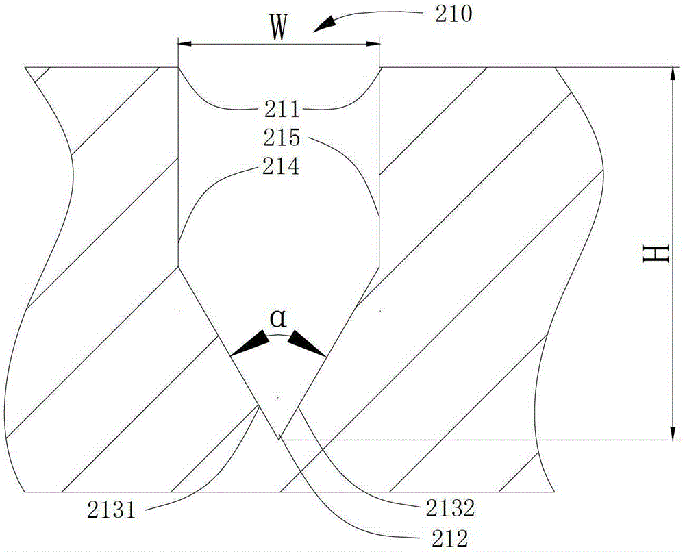
[0043] Please refer to image 3The structure of the first embodiment of the multi-wire cutting machine guide wheel 100 wire groove 210, the wire groove 210 in this embodiment has a groove top 211 close to the outer diameter of the guide wheel 100 and a groove bottom 212 opposite to the groove top 211; the wire groove 210 is in the A V-shaped groove is formed on the axial section of the guide wheel 100. The V-shaped groove has a left side portion 2131 and a right side portion 2132. The left side portion 2131 and the right side portion 2132 are symmetrical to the center line of the wire groove 210 . In addition, a left straight side 214 is connected between the groove top 211 and the left side 2131 , and a right straight side 215 is connected between the groove top 211 and the right side 2132 . Wherein, the left straight portion 214 and the right straight portion 215 are parallel to the center line of the wire groove 210 .

[0044] With this structural design, the axial width ...

Embodiment approach 2

[0049] Please refer to Figure 4 The structure of the second embodiment of the wire groove 310 of the guide wheel 100 of the multi-wire cutting machine. The wire groove 310 in this embodiment has a groove top 311 close to the outer diameter of the guide wheel 100 and a groove bottom 312 opposite to the groove top 311; the wire groove 310 is in the A V-shaped groove is formed on the axial section of the guide wheel 100. The V-shaped groove has a left side portion 3131 and a right side portion 3132. The left side portion 3131 and the right side portion 3132 are symmetrical to the center line of the wire groove 310 . In addition, a left straight portion 314 is connected between the groove top 311 and the left side portion 3131 , and a right straight portion 315 is connected between the groove top 311 and the right side portion 3132 . Wherein the left straight edge portion 314 and the right straight edge portion 315 are parallel to the center line of the trunking. The difference...


PUM

PropertyMeasurementUnit
angleaaaaaaaaaa
radiusaaaaaaaaaa

Abstract

The invention discloses a multi-wire cutting machine guide wheel wire groove and a machining method of the multi-wire cutting machine guide wheel wire groove. A left straight side portion and a right straight side portion are formed by a multi-wire cutting machine guide wheel on the basis of each traditional V-shaped groove, wherein each left straight side portion and each right straight side portion are parallel to the center line of one wire groove. According to the structure, the axial width of each V-shaped groove is reduced, even under the action of the axial acting force F, the cutting steel wire is prevented from generating transitional axial deviation, and therefore the defects of line marks, steps and the like generated on the surface of a crystal slice are reduced. In addition, the cutting steel wire is completely contained in each wire groove through one left straight side portion and one right straight side portion located at the two sides of one V-shaped groove. A component force FS, generated on the side wall of each V-shaped wire groove, of the axial acting force F is weakened due to the fact that the component force FS is restrained by the extrusion force of one left straight side portion or one right straight side portion, so that the difficulty for the cutting steel wire to move towards each groove top is increased, the wire jumping accident of the cutting steel wire is avoided, and therefore the slice quality of the crystal slice in the whole process of production is guaranteed.

Description

technical field [0001] The invention relates to the field of slicing production of semiconductor crystal ingots in the photovoltaic industry, in particular to a guide wheel groove of a multi-wire cutting machine for cutting large-size crystal silicon rods and other semiconductor crystal ingots and a processing method thereof. Background technique [0002] When manufacturing various semiconductors and photovoltaic devices, semiconductor ingots containing hard and brittle materials such as silicon, sapphire, and ceramics are cut and processed into wafers of required thickness. Since wafer dicing is an important process that restricts subsequent finished products, the requirements for its processing are getting higher and higher. At present, multi-wire cutting technology is widely used in the production of crystal slices in the photovoltaic industry due to its high production efficiency, low processing cost, and high processing accuracy. [0003] A pair of guide wheels paralle...

Claims


Application Information

Patent Timeline
Patent Type & Authority Patents(China)
IPC IPC(8): B28D5/04B28D7/00
Inventor 吉鑫周学锋李鹏鲲
Owner GCL POLY ENERGY HLDG
Learn More