Mounting device for push head for maintenance of large and medium-size water-turbine generator set

A technology for generating sets and installation devices, which is applied to hydroelectric power generation, engine components, machines/engines, etc. It can solve problems such as human deviation, low efficiency, and many disadvantages, and achieve the improvement of installation work efficiency, stable lifting, and avoiding rework problems Effect

Active Publication Date: 2013-11-20
STATE GRID CORP OF CHINA +1
View PDF4 Cites 0 Cited by
  • Summary
  • Abstract
  • Description
  • Claims
  • Application Information

AI Technical Summary

Problems solved by technology

[0003] In order to solve the problems of human error, low efficiency and many disadvantages in the installation of the thrust head of the existing large and medium-sized hydro-generator sets, the present invention further proposes a thrust head installation device for large and medium-sized hydro-generator sets during maintenance

Method used


Image

  • Mounting device for push head for maintenance of large and medium-size water-turbine generator set
  • Mounting device for push head for maintenance of large and medium-size water-turbine generator set
  • Mounting device for push head for maintenance of large and medium-size water-turbine generator set

Examples


specific Embodiment approach 1

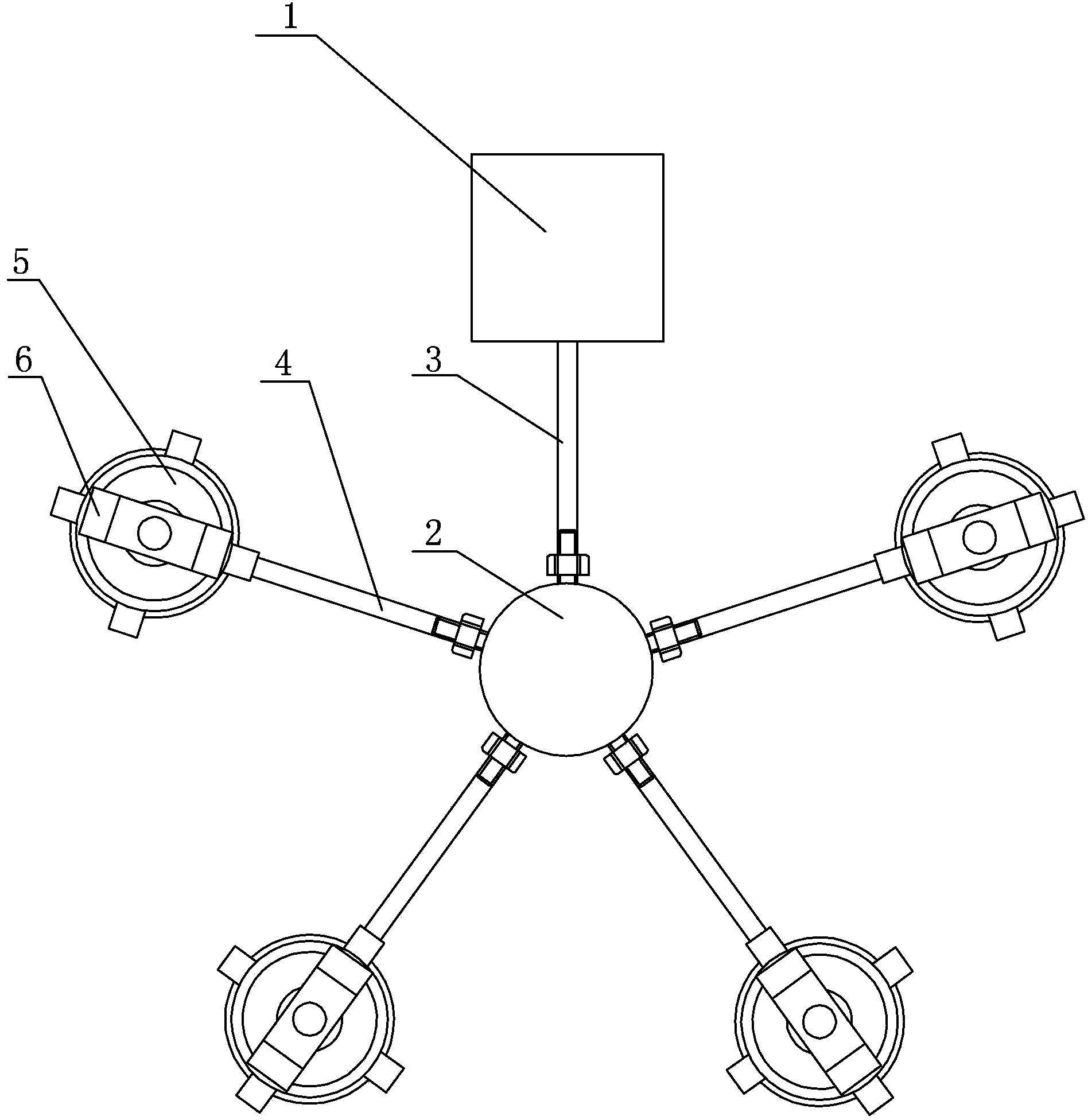
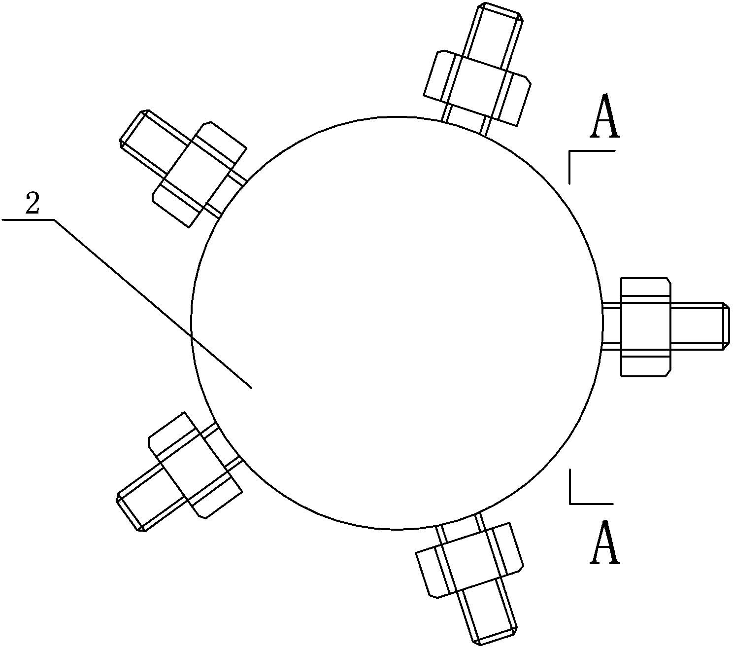
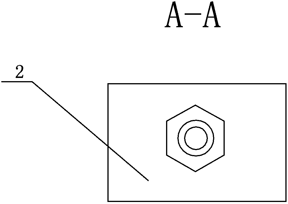
[0007] Specific implementation mode one: combine Figure 1 to Figure 7 This embodiment is described. The thrust head installation device described in this embodiment includes a high-pressure electric oil pump 1, a multi-way joint 2, a main pipeline 3, a plurality of branch pipelines 4, and a plurality of lifting tools 5. and a plurality of fixed frames 6, a plurality of lifting tools 5 are arranged in a circle, a multi-way joint 2 is arranged in the center of the circle, and a fixed frame 6 is respectively fixedly installed on the upper end of each lifting tool 5, and a high-pressure electric oil pump 1 The oil outlet is connected with the oil inlet of the multiway joint 2 through the main pipeline 3, and each oil outlet of the multiway joint 2 is connected with the oil inlet of a corresponding lifting tool 5 through a branch pipeline 4 respectively.

[0008] In this embodiment, the high-voltage electric oil pump 1 is equipped with a pressure relief component, which can releas...

specific Embodiment approach 2

[0009] Specific implementation mode two: combination Figure 4 and Figure 5 Describe this embodiment, a thrust head installation device for large and medium-sized hydroelectric generating units in this embodiment. Each lifting tool 5 includes a lifting main body 5-1 and a lifting push rod 5-2. The lifting push rod 5-2 The lower end is inserted in the lifting main body 5-1, and the upper end of the lifting push rod 5-2 is connected with the lower end of a corresponding fixing frame 6. Other components and connections are the same as those in the first embodiment.

specific Embodiment approach 3

[0010] Specific implementation mode three: combination Figure 6 and Figure 7 To illustrate this embodiment, each fixing frame 6 of the thrust head installation device described in this embodiment is U-shaped, and the bottom of each fixing frame 6 is opened with a through hole 6-1. Other components and connections are the same as those in the first embodiment.


PUM


Abstract

The invention relates to a mounting device for a push head, in particular to a mounting device for a push head for the maintenance of a large and medium-size water-turbine generator set, and solves the problems, for example, the man-made deviation is caused during the mounting of the push head of the traditional large and medium-size water-turbine generator set, the efficiency is low, and the defects are more. The mounting device comprises a high-pressure electric oil pump, a multipass joint, a main pipeline, a plurality of branch pipelines, a plurality of lifting tools and a plurality of fixing brackets, wherein the lifting tools are arranged in a circle with the multipass joint in the center; the upper end of each lifting tool is respectively fixed with one corresponding fixing bracket; an oil outlet of the high-pressure electric oil pump is connected with an oil inlet of the multipass joint through the main pipeline; each oil outlet of the multipass joint is connected with the oil inlet of the corresponding lifting tool through one branch pipeline. The mounting device is used for mounting the push head of the large and medium-size water-turbine generator set.

Description

technical field [0001] The invention relates to a thrust head installation device, in particular to a thrust head installation device for large and medium-sized hydroelectric generating sets. Background technique [0002] Generally known large and medium-sized hydro-generator thrust head is installed, and the method is that after the thrust head is connected to the mirror plate, it falls on the thrust tile, and the rotating parts such as the rotor fall on the brake brake, and then the connecting bolt is passed through on the upper side of the flange. , tighten the bolts with a pneumatic wrench, and lift the thrust head up. The installation process requires the cooperation of multiple people. The bolts are fastened in four symmetrical directions of the flange. Due to the different technical proficiency of the workers and the difference in construction experience, human errors often occur during installation, and repeated installation is required. At the same time, when the b...

Claims


Application Information

Patent Timeline
Patent Type & Authority Applications(China)
IPC IPC(8): F03B11/00
CPCY02E10/226Y02E10/20
Inventor 崔春张瑞勇谢天宇
Owner STATE GRID CORP OF CHINA
Why Eureka
Try Eureka