Fan for electric locomotive auxiliary filter cabinet and electric locomotive

A technology for auxiliary filter cabinets and electric locomotives, which is applied in the field of mechanical structures and can solve problems such as inability to meet heat dissipation requirements

Active Publication Date: 2015-10-21
CRRC YONGJI ELECTRIC CO LTD
View PDF5 Cites 0 Cited by
  • Summary
  • Abstract
  • Description
  • Claims
  • Application Information

AI Technical Summary

Problems solved by technology

[0006] The auxiliary filter cabinet used on the D2C-B passenger car has a special structure, which requires the gas flow in the fan to have a specific directionality. The existing axial flow fan or Centrifugal fans obviously cannot meet the above heat dissipation requirements

Method used


Image

  • Fan for electric locomotive auxiliary filter cabinet and electric locomotive
  • Fan for electric locomotive auxiliary filter cabinet and electric locomotive
  • Fan for electric locomotive auxiliary filter cabinet and electric locomotive

Examples


Embodiment Construction

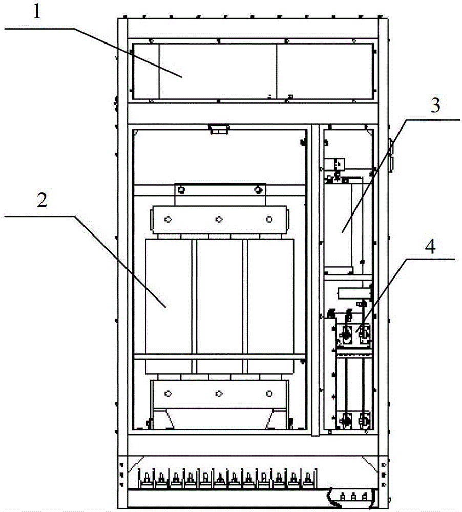
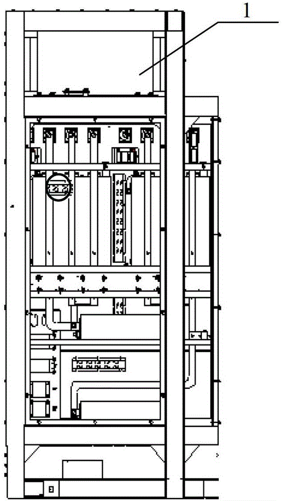
[0037] The embodiment of the present invention provides a fan for cooling electric locomotives, such as auxiliary filter cabinets used on Harmony D2C-B passenger cars and HXD2C locomotives, and equipment with similar structures, referred to in this embodiment The axial direction refers to the axial direction along the guide vane ring or impeller, and the centrifugal direction refers to the centrifugal direction along the guide vane ring or impeller.

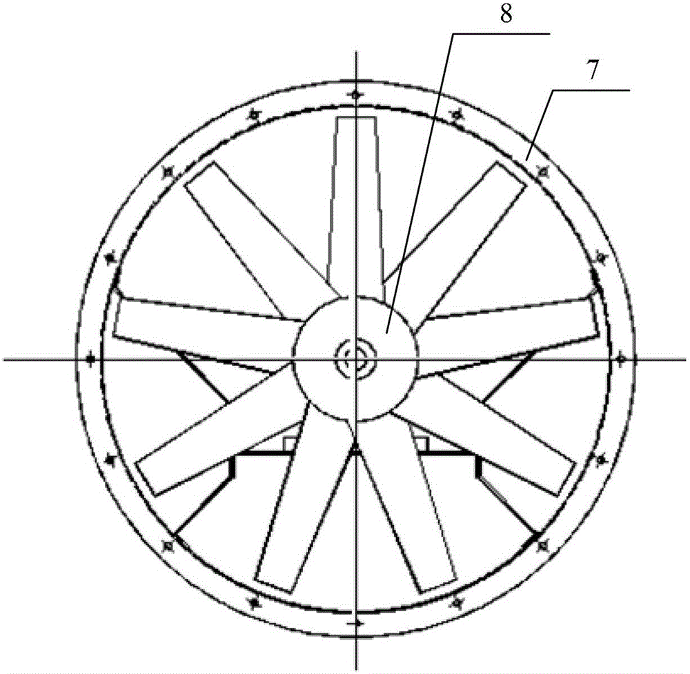
[0038] see Figure 2a , Figure 2b with Figure 2c ,in, Figure 2a A schematic diagram of the front view of the fan used in the auxiliary filter cabinet of the electric locomotive provided by the embodiment of the present invention; Figure 2b for Figure 2a The right view schematic diagram of ; Figure 2c for Figure 2b The schematic diagram of A direction. An embodiment of the present invention provides a fan, including a casing 13 , a motor 14 , a guide vane ring 15 and an impeller 16 . For a schematic diagram of the g...


PUM


Abstract

The invention provides a fan for an auxiliary filter cabinet of an electric locomotive and the electric locomotive. The fan comprises a machine shell, a motor, a guide blade ring, and an impeller, wherein the machine shell is provided with an air inlet, an air outlet, and a cavity communicated with the air inlet and the air outlet, the motor is provided with an output shaft and is fixed at the end, close to the air inlet, of the cavity, the guide blade ring is sealed at the end, close to the air outlet, of the machine shell in a rotating mode, the output shaft penetrates through the guide blade ring, and the impeller is fixed at the end, far away from the machine shell, of the guide blade ring in a sealing mode and is further fixedly connected with the output shaft. The motor rotates so as to enable cooling gas to be absorbed in the cavity through the air inlet. The cooling gas is driven by the guide blade ring and the impeller to be exhausted from the air outlet. By the adoption of the technical scheme, the fan can be adjusted in multiple directions on the condition that the air direction of the fan is not changed, so that the requirements of the locomotive for the air direction of the auxiliary filter cabinet in different working conditions can be met.

Description

technical field [0001] The invention relates to mechanical structure technology, in particular to a fan used for an auxiliary filter cabinet of an electric locomotive and an electric locomotive. Background technique [0002] The HXD2C locomotive is equipped with an auxiliary filter cabinet to filter various signals on the locomotive. [0003] Figure 1a It is a schematic diagram of the front view of the structure of the auxiliary filter cabinet, Figure 1b for Figure 1a side view. see Figure 1a with Figure 1b , taking the direction shown in the figure as the reference direction. see Figure 1a , the auxiliary filtering cabinet is in the shape of a cube as a whole, and the internal space of the auxiliary filtering cabinet can be roughly divided into an upper space, a middle space and a lower space. Among them, the fan 1 is installed in the upper space; the left side of the middle space is the installation space of the auxiliary transformer 2, and the right side is the ...

Claims


Application Information

Patent Timeline
Patent Type & Authority Patents(China)
IPC IPC(8): F04D25/08F04D29/28F04D29/44F04D29/00B61C3/00
Inventor 唐子辉高永军蒋学君卫钢夏楠
Owner CRRC YONGJI ELECTRIC CO LTD
Why Eureka
Try Eureka