A Diagonally Compressed Bistable Plate Piezoelectric Energy Harvesting Device

A piezoelectric energy collection device technology, applied in the direction of piezoelectric effect/electrostrictive or magnetostrictive motors, electrical components, generators/motors, etc. Bistable structure, low energy collection efficiency and other issues, to achieve the effect of improving energy collection efficiency, simple structure, and strong practicability

Active Publication Date: 2019-06-04
HEFEI UNIV OF TECH
View PDF7 Cites 1 Cited by
  • Summary
  • Abstract
  • Description
  • Claims
  • Application Information

AI Technical Summary

Problems solved by technology

[0006] The present invention solves the defects of narrow operating frequency band and low energy collection efficiency in existing piezoelectric energy harvesting devices based on linear system design, introduces electromagnetic interference into bistable piezoelectric energy harvesting devices based on nonlinear permanent magnetic force, and avoids magnets. The bistable piezoelectric energy harvesting device can only adjust the axial compression force in one direction, it is difficult to realize the bistable structure, and it is difficult to exert the piezoelectric characteristics of piezoelectric materials, and the power generation efficiency is low. It provides a magnet-free diagonal Compressive bistable plate piezoelectric energy harvesting device

Method used


Image

  • A Diagonally Compressed Bistable Plate Piezoelectric Energy Harvesting Device
  • A Diagonally Compressed Bistable Plate Piezoelectric Energy Harvesting Device
  • A Diagonally Compressed Bistable Plate Piezoelectric Energy Harvesting Device

Examples


Embodiment 1

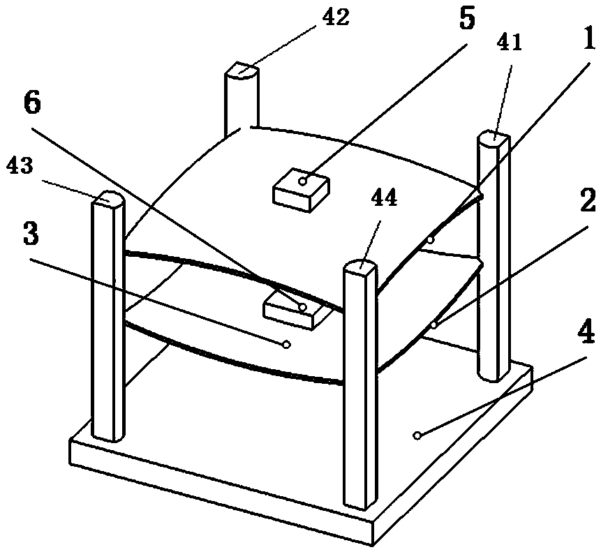
[0023] This embodiment provides an example of a diagonally compressed bistable plate piezoelectric energy harvesting device, and its structural schematic diagram is as follows figure 1 shown in .

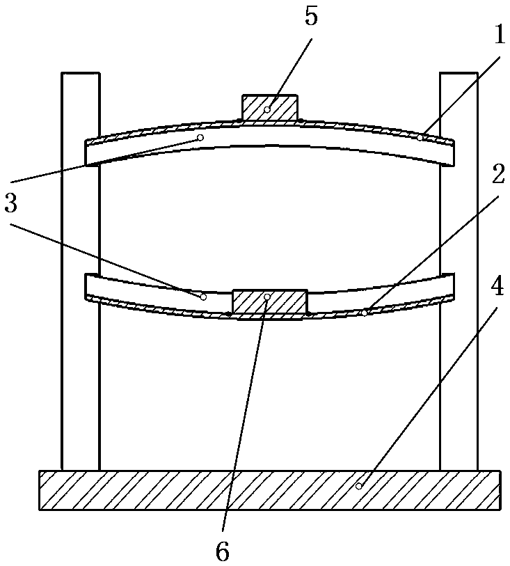
[0024] The diagonally compressed bistable plate piezoelectric energy harvesting device includes one or more rectangular plate-shaped piezoelectric energy harvesting units, and clamps the edge of the piezoelectric energy harvesting unit and provides centripetal force to the piezoelectric energy harvesting unit. Clamp 4 for compressive force;

[0025] The piezoelectric energy harvesting unit includes a rectangular plate-shaped flexible rectangular plate, and a flexible piezoelectric element 3 attached to the surface of the flexible rectangular plate;

[0026] The fixture 4 is provided with one or more clamping device groups, and the number of the clamping device groups is the same as the number of the piezoelectric energy harvesting units and corresponds to each other; the clamping d...

Embodiment 2

[0038] This embodiment provides an example of specific parameters of a diagonally compressed bistable plate piezoelectric energy harvesting device, the structure of which is the same as that of Embodiment 1.

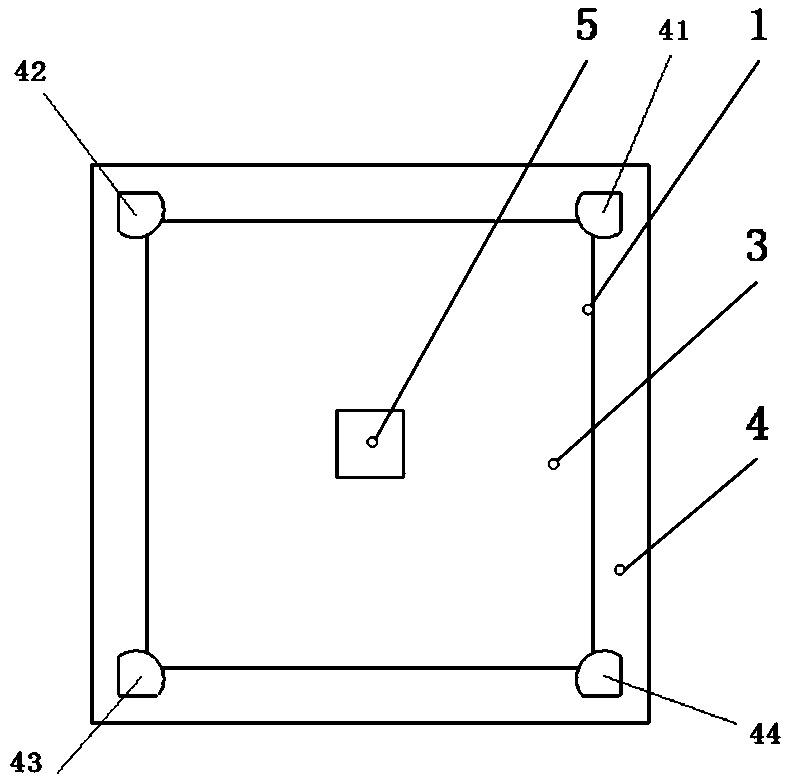
[0039] In this embodiment, the thickness of the flexible rectangular plate is 1 cm, and the length and width are both 11 cm. The height of clamp arm one 41, clamp arm two 42, clamp arm three 43 and clamp arm four 44 is 40 centimeters; the length and width corresponding to the bottom surface of clamp 4 are 10 centimeters. The distance between the grooves on the first clamp arm 41 , the second clamp arm 42 , the third clamp arm 43 and the fourth clamp arm 44 from the bottom of the clamp is 15 centimeters and 30 centimeters. Since the distance from clamp arm one 41 to clamp arm three 43 and the distance from clamp arm two 42 to clamp arm four 44 are 10 centimeters, they are all less than the diagonal length 11 of piezoelectric energy harvesting unit one 1 and piezoelectric ...


PUM


Abstract

A diagonal compression bistable plate-type piezoelectric energy collection device comprises one or more than one rectangular plate piezoelectric energy collection unit, and a clamp configured to clamp the edge of the piezoelectric energy collection unit and provide centripetal compression force to the piezoelectric energy collection unit. The piezoelectric energy collection unit comprises a rectangular plate flexible rectangular plate and a flexible piezoelectric element applied to the surface of the flexible rectangular plate. Compared to the commonly employed axial direction compression single-layer bistable plate-type piezoelectric energy collection device, the diagonal compression bistable plate-type piezoelectric energy collection device can realize multidirectional regulation, and has wider frequency response range and higher output power; and moreover, the clamp is employed to perform centripetal compression force regulation at the flexible rectangular plate angular point, the flexible piezoelectric element applied to the surface of the flexible rectangular plate is more uniform so as to give full play to piezoelectric characteristics of piezoelectric materials and improve the generation efficiency.

Description

technical field [0001] The invention belongs to the field of piezoelectric energy collection, in particular to a bistable plate piezoelectric energy collection device. Background technique [0002] Nowadays, the application of sensor network is very common, and the development of Internet of things technology has promoted the use of sensor network. With the development of electronic technology and other related fields, sensors with lower and lower power consumption have been realized, the energy supply requirements of sensor networks have been reduced, and the power of some sensor networks has been reduced to the order of milliwatts. [0003] The sensor network is mainly powered by chemical batteries. Although the power consumption of the sensor network can be reduced to extend the battery life, the replacement of the battery will cost a lot of money, and it is almost impossible to replace the battery in some very large sensor networks. In order to overcome the problems cau...

Claims


Application Information

Patent Timeline
Patent Type & Authority Patents(China)
IPC IPC(8): H02N2/18
CPCH02N2/186
Inventor 邓华夏王哲敏杜宇于连栋张进马孟超钟翔
Owner HEFEI UNIV OF TECH
Why Eureka
Try Eureka