
Material compressing device, material compressing method thereof and sintering machine pallet

A material compaction, machine trolley technology, applied in lighting and heating equipment, furnace types, furnaces, etc., can solve the problems of loose material compaction and poor use effect.

Active Publication Date: 2013-11-20
PANGANG GRP XICHANG STEEL & VANADIUM CO LTD
View PDF8 Cites 4 Cited by
  • Summary
  • Abstract
  • Description
  • Claims
  • Application Information

AI Technical Summary

Problems solved by technology

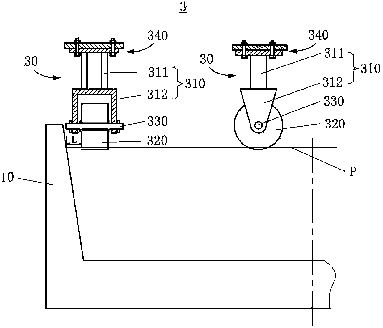
[0006] As mentioned above, since the pressing wheel 320 in the structure of the material pressing unit 30 in the prior art is fixedly connected with the main body 310 by the connecting shaft 330, the pressing wheel cannot move freely with the thickness of the material layer.
In addition, due to the double support structure, limited by the elongation length of the connecting shaft 320, the end surface of the pressure roller 320 has a certain distance from the trolley fence 10, which becomes a restricted area L for pressing material, and the pressure wheel 320 cannot press the limited area. The loose material of L is compacted, and the actual use effect is poor

Method used


Image

  • Material compressing device, material compressing method thereof and sintering machine pallet
  • Material compressing device, material compressing method thereof and sintering machine pallet
  • Material compressing device, material compressing method thereof and sintering machine pallet

Examples


Embodiment Construction

[0022] Examples of embodiments of the present invention will now be described in detail with reference to the accompanying drawings. In the accompanying drawings, for clarity, the regions or elements in the drawings will be exaggerated, and elements are not necessarily drawn to scale, and the same reference numerals always indicate the same elements or structures.

[0023] Different from the prior art dual-support fixed material pressing device, the material pressing device according to the embodiment of the present invention has a simpler structure, which can not only approach the trolley fence to the maximum, so that the edge loose materials can be effectively compressed, but also operate Flexible, good sealing, and the pressure wheel can move up and down with the articulated movement of the movable force arm. The edge of the pressure wheel is always in contact with the material surface. At the same time, it is free to increase or decrease the counterweight on the force arm to im...


PUM


Abstract

The invention relates to a material compressing device, a sintering machine pallet and a material compressing method of the material compressing device. The material compressing device comprises at least one material compressing unit. The material compressing unit comprises a link arm, a compressing wheel, a bearing component and a fixed seat. The link arm is provided with a hinge hole and a connection hole, arranged at one side of the compressing wheel, and forms cantilever shaft unilateral support. The compressing wheel carries out compressing operation on materials. The bearing component is assembled in the pressing wheel. The pressing wheel is connected with the connection hole of the link arm through a connecting shaft of the bearing component. The fixed seat is provided with a supporting body and a movable hinge seat, wherein the movable hinge seat is hinged to the link arm through the hinge hole and used for supporting the link arm.

Description

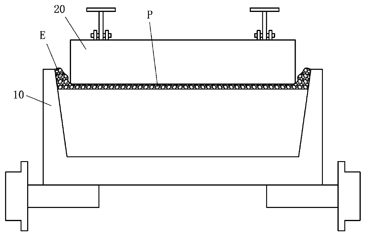
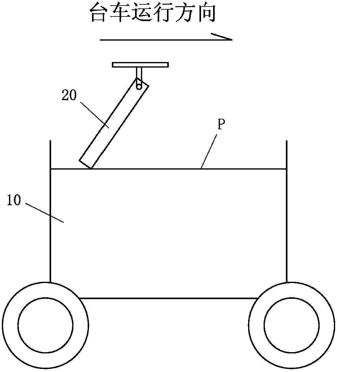
Technical field [0001] The invention relates to a material pressing device, a material pressing method thereof, and a sintering machine trolley, and more specifically, to a device capable of flexibly and maximally close to the edge to compact loose materials, and a material pressing method thereof. Sintering machine trolley using this material compaction device. Background technique [0002] The sintered mixture material is distributed to the trolley through the distributor, and the surface material is reshaped, flattened and compressed by the leveling device. During this process, the excess materials will accumulate on both sides of the trolley fence, forming "dead corners" (such as figure 1 “E” in the edge of the loose material surface), because the edge material has not undergone shaping and compaction, the material and the trolley fence are poorly sealed, and the air leakage phenomenon is serious during the sintering process, causing the edge material to burn incompletely. Qu...

Claims


Application Information

Patent Timeline
Patent Type & Authority Applications(China)
IPC IPC(8): F27B21/08
Inventor 吴坚凌碧熔
Owner PANGANG GRP XICHANG STEEL & VANADIUM CO LTD
Learn More