Modeling Method of Space Manipulator Based on Differential Geometry
What is AI technical title?
AI technical title is built by PatSnap AI team. It summarizes the technical point description of the patent document.
A technology of space manipulators and modeling methods, applied in special data processing applications, instruments, electrical digital data processing, etc., can solve problems such as lack of research results and methods
Active Publication Date: 2016-03-23
HARBIN INST OF TECH
View PDF3 Cites 0 Cited by
Summary
Abstract
Description
Claims
Application Information
AI Technical Summary
This helps you quickly interpret patents by identifying the three key elements:
Problems solved by technology
Method used
Benefits of technology
Problems solved by technology
In the research process of the space manipulator, there is a requirement that the model of the space manipulator established can not only ensure the calculation efficiency and accuracy of the model, but also have a clear physical meaning. At present, there are no similar research results and methods in the literature search
Method used
Image
Click on the blue label to locate the original text in one second.
Reading with bidirectional positioning of images and text.
Examples
Embodiment 1
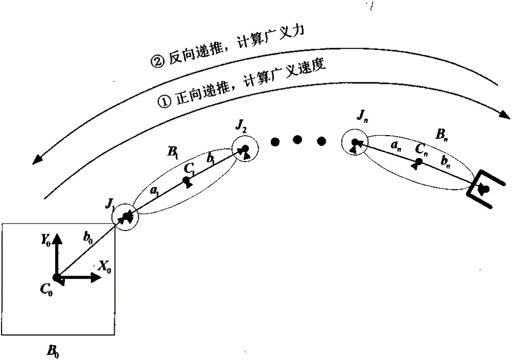
[0067] Example 1, combining figure 1 , the steps of the differential geometry-based modeling method of the present invention are as follows:
[0068] Step 1: Select the zero position of the robotic arm system, and write the zero position joint vector S∈se(3), the mass center joint vector r, and the inertia matrix I.
[0069] Step 2: Calculate the positive definite symmetric matrix J related to the inertial parameters, and the coordinate position matrix M∈SE(3).
[0070] Step 3: Calculate the generalized velocity of each connecting rod by forward recursion.
[0071] Step 4: Given the generalized force F acting on the end effector n+1 , the generalized force of each connecting rod is calculated by reverse recursion.
[0072] Step 5: Write each quantity as a matrix expression to obtain the dynamic equation in compact form.
Embodiment 2
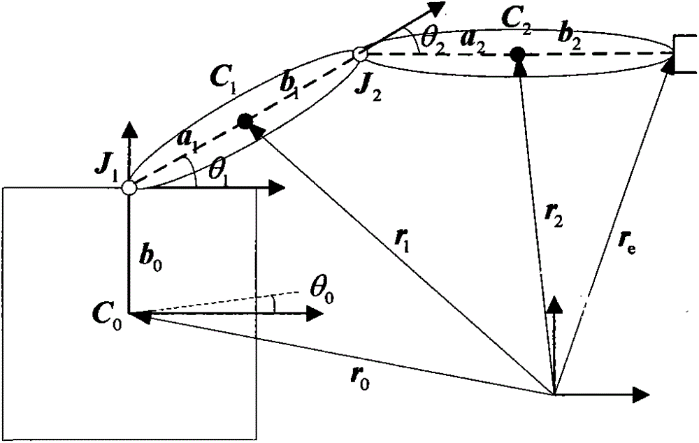
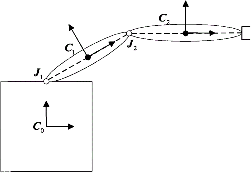
[0073] Example 2, combined figure 1 , figure 2 , the zero position of the robotic arm system studied by the present invention is selected in this way, the center of mass of the base and each link joint are selected as the origin of the base and the fixed connection coordinate system of the connecting rod at all levels, and the base coordinate system is recorded as 0 number, the connecting rods at all levels are marked as i (i=1,...,n), the fixed coordinate system of the end effector is marked as number (n+1), and the origin is selected at the end of the connecting rod. According to the robotics convention, the variables of each link joint are defined as
[0074]
[0075] with q i =0 is zero bit.
[0076] For the plane 2R free-flying space manipulator system, the zero joint vector S i =[001000] T ; centroid position vector r 0 =[000] T , r 1 =[a 1 00] T , r 2 =[a 2 00] T , where a 1 , a 2 respectively are the geometric parameters shown in the figure; the iner...
Embodiment 3
[0077] Example 3, combined figure 1 , figure 2 , the matrix J and the coordinate position matrix M∈SE(3) defined by the present invention are calculated as follows,
[0078] J i = I i - m i r ~ i 2 m i r ~ i - m i r ~ ...
PUM
Abstract
The invention discloses a space manipulator modeling method based on different geometry. On the foundation that each level rigid body zero position of a space manipulator system is selected, initializing conditions such as a zero position joint vector, a centroid joint vector and an initial vector are calculated and given, and a matrix related to initial parameters and a coordinate position matrix are calculated. The generalized velocity of each connecting rod is calculated through forward recursion, and the generalized force of each connecting rod is calculated through reverse recursion. Each quantity is substituted into the matrixes, and a kinetic equation compact in form is written down. The model has the advantages of being uniform in modeling form and small in operating amount, improving calculation efficiency and accuracy of the space manipulator modeling, and improving the designing accuracy of the space manipulator. The space manipulator modeling method based on differential geometry can be applied to modeling of other space multi-rigid-body systems.
Description
technical field [0001] The invention belongs to the field of space manipulator model construction, in particular to a differential geometry-based modeling method of a space manipulator. Background technique [0002] As a spacecraft on-orbit maintenance equipment, the space manipulator can complete many tasks such as spacecraft maintenance, fuel replenishment, material transportation, and space garbage cleaning, and plays an important role in space activities. [0003] In the process of design and demonstration of space manipulator, accurate and simple mathematical model is the basis of research. However, the space manipulator works in a weightless environment in space, and there is a high degree of coupling between the floating base and the manipulator link. At the same time, due to the consideration of the economic cost caused by launching objects into space, the volume, mass and energy consumption of the space manipulator are greatly limited. Therefore, the traditional g...
Claims
Application Information
Patent Timeline
Application Date:The date an application was filed.
Publication Date:The date a patent or application was officially published.
First Publication Date:The earliest publication date of a patent with the same application number.
Issue Date:Publication date of the patent grant document.
PCT Entry Date:The Entry date of PCT National Phase.
Estimated Expiry Date:The statutory expiry date of a patent right according to the Patent Law, and it is the longest term of protection that the patent right can achieve without the termination of the patent right due to other reasons(Term extension factor has been taken into account ).
Invalid Date:Actual expiry date is based on effective date or publication date of legal transaction data of invalid patent.

