OBM-based road tunnel design method
A technology of highway tunnel and design method, applied in the direction of tunnel, design optimization/simulation, calculation, etc., can solve the problem of small size of 3D model, achieve significant economic and social benefits, facilitate operation, improve design accuracy and modeling efficiency Effect
Active Publication Date: 2019-03-29
HENAN PROVINCIAL COMM PLANNING & DESIGN INST CO LTD
6 Cites 10 Cited by
AI-Extracted Technical Summary
Problems solved by technology
[0005] In view of the above situation, in order to overcome the defects of the prior art, the purpose of the present invention is to provide a road tunnel design method based on OBM, which can effectively solve the problem of c...
Method used
Described setting up different surrounding rock cross-section formwork library of tunnel, feature definition library as the resource library file that enterprise self accumulates, can carry out reuse at later stage, cooperate file management mode to reduce BIM technology popularization and use cost, improve design efficiency , realize the value of BIM technology;
The present invention is through on-the-spot application and test, and effect is very good, compared with adopting Revit software, convenient operation is fast, saves time more than 2 times, can improve design precision and modeling efficiency, and precision reaches 99%, and modeling efficiency improves More than 50%, the volume of the generated 3D model is small, only 1/3 of the volume of the original 3D model, which is easy to meet the needs of splitting and data sorting of the later construction model. Check tunnel design problems through 3D design, improve design quality, and avoid construction problems caused by design; in view of the practical requirements of information engineering, a 3D tunnel design method based on BIM technology with clear logic and strong operability is provided, which can provide The model accuracy and information coding tu...
Abstract
The invention relates to an OBM-based road tunnel design method. The purposes are effectively achieved that the operation is convenient, the design precision and the modeling efficiency are improved,the size of a generated three-dimensional model is small, and the demands for splitting and data sorting of a later construction model are easily met. A tunnel three-dimensional terrain, a three-dimensional geological model are created, and tunnel surrounding rock division is conducted; a tunnel three-dimensional route model is established according to route design data; a tunnel cross section isdesigned, and a tunnel cross section template library is created; layout span lines are utilized for arrangement of surrounding rock pile numbers of a tunnel, and tunnel main hole, transverse channeland inclined well models are established; tunnel portal, portal side slope protector, steel bar, steel frame and tunnel anchor rod models are established; tunnel electromechanical, fire fighting, inner and outer prevention drainage and traffic engineering models are established; the transverse channel and main hole models are subjected to trimming modeling, a transverse channel is subjected to portal forming modeling in a main hole structure, the vehicle-passing transverse channel is subjected to sinking cable groove treatment, tunnel emergency stop widening modeling is conducted, and the tunnel model and the geological model are combined for modeling; the tunnel model is split, and tunnel components are coded.
Application Domain
Design optimisation/simulationTunnels +1
Technology Topic
TerrainThree dimensional model +10
Image
Examples
- Experimental program(1)
Example Embodiment
[0017] The specific implementation of the present invention will be described in detail below in conjunction with the accompanying drawings and specific conditions.
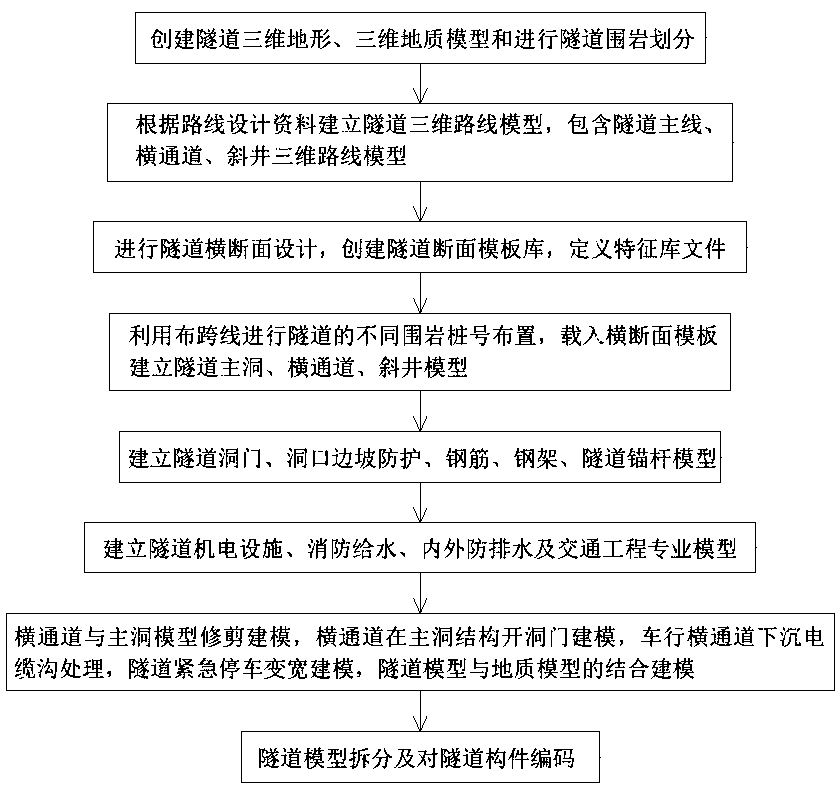
[0018] Depend on figure 1 Shown, a kind of highway tunnel design method based on BIM of the present invention, in concrete implementation, can be given by the following steps:
[0019] (1) Create a 3D terrain and 3D geological model of the tunnel and divide the surrounding rock of the tunnel:
[0020] Create three-dimensional terrain of the tunnel: According to the data surveying and mapping data of UAV and laser radar aerial survey, topographic map and image data, through element filtering and extraction of contour lines, a complete regional terrain surface model is established;
[0021] Create a 3D geological model: According to the geological data provided by the geological exploration equipment, enter the drilling data into the database, establish a columnar model of the rock formation, generate different rock layers through the same rock layer and the boundary of the project scope, and cut the thickened terrain with different rock layers in the tunnel section Entity model, establish different geological body models, and assign different geological rock layer attribute data respectively, and establish project geological data model data; divide the tunnel surrounding rock according to geological survey data, design specifications, and overall route design data;
[0022] (2) Establish a three-dimensional route model of the tunnel according to the route design data, including the three-dimensional route model of the main line of the tunnel, the transverse passage, and the inclined shaft;
[0023] According to the overall design file, import the route design data to generate a three-dimensional file of the main line of the tunnel route. The tunnel route that does not contain horizontal and vertical data includes transverse passages and inclined shafts, which need to be in the software OBM (bridge 3D modeling software; English OpenBridgeModeler abbreviation) According to the plane line position and longitudinal section data, you can customize the addition, draw the plane line and edit the slope and elevation of the longitudinal section, and establish a three-dimensional route design model of the tunnel;
[0024] (3) Carry out tunnel cross-section design, create a tunnel section template library, and feature definition library files:
[0025] Tunnel cross-section design: creating a tunnel section template library refers to extracting the outer contour lines of components as closed surfaces according to different surrounding rock sections and design drawings to realize template production; by unifying template reference points into surveying lines and design elevation points The intersection point of the horizontal line of the template is used as the reference point for stretching and lofting of the template; according to the splitting rules of the tunnel components, the different components of each cross-section are named respectively, and the different line elements are connected into a closed section by line combination and saved to establish all types of cross-sections of the tunnel project Template library; the template library includes four types: main hole, transverse passage, inclined shaft and shear body; for components that need to be widened, add parameter control points and constraint relationships in the template to establish a parameter control template;
[0026] Create a feature definition library: Create a new tunnel feature under the corresponding file in the standard library, including the new layer name, color, material feature and filling picture, grade strength information, and complete the feature definition library file of the custom component;
[0027] (4) Use spanning lines to arrange different surrounding rock pile numbers of the tunnel, and load the cross-section template to establish tunnel main tunnel, cross passage, and inclined shaft models:
[0028] Use spanning lines to arrange different surrounding rock pile numbers of tunnels: Create a new project file in the software OBM (bridge three-dimensional modeling software; English OpenBridge Modeler abbreviation), activate the target route, and use the spanning line tool to arrange different surrounding rocks of the tunnel project Stake number;
[0029] Load the cross-section template to establish the tunnel main tunnel, cross passage, and inclined shaft model: select the cross-section template of the target mileage section, and realize the positioning of the template by locating the reference point of the cross-section in the template to correspond to the route in the actual tunnel model, and select The feature definition corresponding to the component is used to select the material and add other information, and establish the tunnel component model, including the main tunnel component, cross channel component, inclined shaft component and shear body component;
[0030] (5) Establish models of tunnel portals, portal slope protection, steel bars, steel frames, and tunnel anchors:
[0031] Establish tunnel entrance and entrance slope protection models: the entrance slope protection geological body adopts different slope surface structures and performs Boolean operation and difference set with the geological model to obtain the entrance slope protection model, and establishes the tunnel entrance model according to the entrance design drawings, combined with Tunnel main line and topography, geological models to place portals, portal slope protection models;
[0032] The Boolean operation difference set is that when there are intersecting and overlapping parts between the two solid models, the intersecting and overlapping parts are removed, leaving the remaining part of the two solid models, which is the Boolean operation taking the difference set:
[0033] Steel bars, steel frames, and tunnel anchor models: According to the design drawings and the 3D tunnel route model, respectively establish steel bar units, steel frame units, and anchor rod units for different surrounding rock sections, make a tunnel project unit library, and select the stake number position after calling the units. placed in the tunnel model;
[0034] (6) Establish professional models of tunnel mechanical and electrical facilities, fire water supply, internal and external waterproofing and drainage, and traffic engineering:
[0035] Construct two types of models, the first type is to make part of the model as an independent unit, set the reference point of the new unit to be the same as the reference point of the cross-section of the tunnel main tunnel member, select the initial pile number along the path direction, set the unit spacing, establish electromechanical facilities, Horizontal unit models for fire water supply, internal and external waterproofing and drainage, and traffic engineering; the second type is to establish a cross-sectional template for pipelines, and establish a longitudinal electromechanical model by stretching and lofting along the path;
[0036] (7) Trimming and modeling of the cross passage and the main tunnel model, modeling of the opening of the cross passage in the main tunnel structure, treatment of the sinking cable trench of the cross passage for vehicles, modeling of emergency parking and widening of the tunnel, and integration of the tunnel model and the geological model Combined modeling:
[0037] The pruning modeling of the cross passage and the main hole model refers to the establishment of the contour solid segment in the main hole and the cross passage model to perform Boolean operations;
[0038] Modeling of the opening door of the cross passage in the main cave structure: refers to the establishment of the outer contour solid segment of the cross passage and the part of the main cave components to perform Boolean operations to complete the modeling of the opening door of the cross passage on the inner wall of the main cave;
[0039] The sinking cable trench treatment of the vehicle cross passage refers to the establishment of a solid model of the sinking area, including four parts: the baffle plate of the eight-shaped cable trench structure on both sides, the cover plate structure of the sinking cable trench, and the shear body of the sinking area; placing the cable trench structure and For the solid model of the sinking cable trench cover plate, Boolean operations are performed on the shearing body of the sinking area, the cable trench structure and the cover plate, and the processing of the sinking cable trench model of the vehicle cross passage is completed;
[0040] Tunnel emergency parking widening modeling refers to combining the cross-section template with parameter control in step (3), through the linkage of control parameter points, setting the horizontal and vertical parameters of the control points, and setting the widening or narrowing to the value in the parameter control interface, Complete the widening or narrowing component modeling of the emergency parking belt;
[0041] The combined modeling of the tunnel model and the geological model refers to the tunnel shear body template for the initial support outer wall contour of the tunnel main cavity structure, the shear body template for the initial support outer wall contour of the tunnel cross passage structure, and the inclined shaft Outer wall contour shear body formwork for initial support of the structure, implementation conditions Establish the outer contour solid models of all primary support components of the tunnel according to the tunnel route, perform Boolean operations on the solid and all geological models, and respectively establish the geological bodies around the tunnel and the geological bodies for tunnel excavation Model;
[0042] (8), Tunnel model splitting and coding of tunnel components:
[0043]Tunnel model splitting refers to splitting the tunnel model, splitting the tunnel model according to each linear meter, adding the equidistant spanning lines of the target pile number section, splitting the tunnel components by cutting entities, and establishing the split components of the tunnel model;
[0044] Coding of tunnel components: through the development of coding plug-ins for the 3D model established by OBM software, engineering coding is carried out for each tunnel component, and the names of tunnel sub-items are pre-edited and sorted out. In the component attribute column, it is passed to the management platform as a unique component code.
[0045] A kind of highway tunnel design method based on BIM of the present invention, in concrete implementation, also can be provided by following steps:
[0046] (1) Create a 3D terrain and 3D geological model of the tunnel and divide the surrounding rock of the tunnel:
[0047] According to the data surveying and mapping data topographic map and image data of unmanned aerial vehicle flight and lidar aerial survey, use the element filtering function to extract the terrain contour line and elevation point data elements in the aerial survey data, and automatically extract all the elements near the elevation point, with three element points to form a triangular surface to generate a complete regional topographic surface model;
[0048] After the terrain model is completed, according to the geological data of the project provided by the geological exploration equipment, the drilling data is entered into the database, and the columnar model of the rock formation is established. Different rock layers are generated through the same rock layer and the boundary of the project scope, and different rock layers in the tunnel section are used to cut thickened tunnels. Terrain entity model, establish different geological body models, and assign attribute information of different geological rock formations respectively, establish project geological data model data, and divide tunnel surrounding rock according to geological survey data, design specifications, and overall route design data;
[0049] (2) Establish a three-dimensional route model of the tunnel based on the route design data, including the three-dimensional route model of the main line of the tunnel, the transverse passage, and the inclined shaft:
[0050] According to the horizontal and vertical data of the route generated by the overall design file, import the three-dimensional design software to generate the three-dimensional model of the main line of the tunnel route. Wherein, when the horizontal and vertical data of the main line of the route do not include the horizontal and vertical data of the tunnel cross passage and the horizontal and vertical data files of the inclined shaft, then It is necessary to customize and add according to the plane line position and longitudinal section data, draw the plane line and edit the slope and elevation of the longitudinal section, then activate the longitudinal section and save the project route file to establish a 3D route model of the tunnel;
[0051] (3) Carry out tunnel cross-section design, create tunnel section template library, and feature definition library files;
[0052] According to different surrounding rock sections, import different cross-sectional views into newly created template files, and the template library file categories are divided into four categories: main tunnel, transverse passage, inclined shaft and shear body;
[0053] Among them, the main tunnel formwork library includes the structural components of the tunnel main tunnel, which are sprayed concrete formwork, second-lined arch wall formwork, second-lined inverted arch formwork, left cable trench formwork, right cable trench formwork, and left cable trench cover plate formwork , right cable trench cover formwork, central drainage ditch formwork, central drainage ditch cover formwork, inverted arch backfill formwork, pavement base course formwork, pavement cement concrete layer formwork, pavement asphalt layer formwork, tunnel decoration model;
[0054] The form library of the cross aisle includes the sprayed concrete form for the cross aisle, the formwork for the second lining arch wall of the cross aisle, the backfilling form for the inverted arch of the cross aisle, and the formwork for the pavement structure layer of the cross aisle;
[0055] Inclined shaft template library includes inclined shaft shotcrete template, inclined shaft second lining arch wall template, inclined shaft pavement structural layer template;
[0056] The shear body template includes the inner contour template of the inner wall of the main cave, the outer wall contour template of the primary support of the main tunnel structure, the inner contour template of the inner wall of the emergency parking zone, the outer contour template of the pedestrian cross passage, the outer contour template of the vehicle cross passage, and the initial support of the inclined shaft Outer wall profile template;
[0057] By referring to the design drawings and extracting the outer contour lines of the components as the closed surface to realize the template making, the reference point of the template is unified as the intersection point of the horizontal line between the surveying line and the design elevation point, which is used as the reference point of the template stretching and lofting, according to the splitting rules of the tunnel components , respectively name the different components of each cross-section, use line combinations to connect different line elements into closed sections and save them, and establish template libraries for all types of cross-sections in tunnel projects;
[0058] Conventional tunnel formwork does not need to add parameter control points, which is characterized in that the tunnel structure does not change along the tunnel path, and another tunnel component needs to be widened or narrowed at the start and end of the tunnel emergency stop zone to match the design Such templates include: cable trench structure and cable trench cover templates at the far end of the emergency parking zone from the reference point, all road surface structure templates in the emergency parking zone, add local parameter control points to the above-mentioned templates, and select control points , add constraints, and establish a tunnel cross-section template with parameter control;
[0059] Define the material characteristics of the components required for the tunnel project in the material library file, open the specific material characteristic library file, and create new tunnel characteristics under the corresponding file in the standard, including the new layer name, color, material characteristics and filling pictures, and grade strength Information, complete the feature definition library file of the custom component;
[0060] The template library and feature definition library of different surrounding rock cross sections of the tunnel described above can be used as the resource library files accumulated by the enterprise itself, which can be reused in the later stage, cooperate with the file management mode to reduce the cost of BIM technology promotion and use, improve design efficiency, and realize BIM technical value;
[0061] (4) Use spanning lines to arrange different surrounding rock pile numbers of the tunnel, and load the cross-section template to establish tunnel main tunnel, cross passage, and inclined shaft models:
[0062] Create a new project file, activate the tunnel route, use the spanning line tool to arrange the pile numbers of different surrounding rock sections of the tunnel project, select the tunnel cross-section template of the target mileage section, and locate the reference point of the cross-section in the template to correspond to the route in the actual tunnel model To realize the positioning of the template, and select the corresponding feature definition of the component to realize the addition of materials and other information, and establish the tunnel component model, including the main tunnel component, cross channel component, inclined shaft component and shear body component;
[0063] (5) Establish models of tunnel portals, portal slope protection, steel bars, steel frames, and tunnel anchors:
[0064] According to the design drawings and the three-dimensional route model of the tunnel, respectively establish steel bar units, steel frame units, and anchor units for different surrounding rock sections, make a tunnel project unit library, select the pile number position after calling the unit, and place it in combination with the tunnel model to establish the slope protection geology at the entrance of the tunnel After adopting different slope surface structures and performing Boolean operations with the geological model, the entrance slope protection model is obtained, and the tunnel entrance model is established according to the entrance design drawings, and the tunnel main line and terrain are connected, and the geological model is placed on the entrance and the entrance slope protection model;
[0065] (6) Establish professional models of tunnel mechanical and electrical facilities, fire water supply, internal and external waterproofing and drainage, and traffic engineering:
[0066] There are two types of construction methods, including making part of the model as an independent unit, setting the reference point of the new unit to be the same as the reference point of the cross-section of the tunnel main tunnel member, selecting the initial pile number along the path direction, setting the unit spacing, establishing electromechanical facilities, fire water supply , internal and external waterproofing and drainage, and traffic engineering transverse unit models; the second type is to establish a pipeline-like cross-section template, and stretch and stake out along the path to establish a longitudinal electromechanical model;
[0067] As a pre-built unit library file, including fan unit, bridge bracket unit, tunnel identification signage unit, sand sinking well unit, inspection well unit, horizontal drainage pipe unit, lamp unit, reflective tape unit, cross passage door unit; vertical facilities include bridge frame Model, fire water supply pipe model, and longitudinal drainage pipe model are used to establish tunnel ancillary facility models according to the actual design parameter values of highway tunnel ancillary facilities;
[0068] (7) Trimming and modeling of the cross passage and the main tunnel model, modeling of the opening of the cross passage in the main tunnel structure, treatment of the sinking cable trench of the cross passage for vehicles, modeling of emergency parking and widening of the tunnel, and integration of the tunnel model and the geological model Combined modeling:
[0069] Tunnel model detail processing, including parts and processing methods:
[0070] Model trimming of the cross passage and the main hole: establish the contour entity segment in the main hole and the cross passage model to perform Boolean operation to take the difference;
[0071] The Boolean operation difference set is that when there are intersecting and overlapping parts between the two solid models, the intersecting and overlapping parts are removed, leaving the remaining part of the two solid models, which is the Boolean operation taking the difference set:
[0072] Modeling of the opening door of the cross passage in the main cave structure: establish the solid section of the outer contour of the cross passage and perform Boolean operations on some components of the main cave, and complete the modeling of the opening door of the cross passage on the inner wall of the main cave;
[0073] Treatment of the sinking cable trench in the cross passage of vehicles: establish a solid model of the sinking area, including four parts: the baffle plate of the eight-shaped cable trench structure on both sides, the cover plate structure of the sinking cable trench, and the shear body of the sinking area, and place the cable trench structure and the lower The solid model of the cover plate of the sinking cable trench, the shear body of the sinking area, the structure of the cable trench and the cover plate are respectively subjected to Boolean operations, and the model processing of the sinking cable trench of the vehicle cross passage is completed;
[0074] Treatment of widening or narrowing of the 5-meter section from the start and end of the emergency stop of the tunnel: Use the parameter-controlled cross-section template in step (3), set the horizontal and vertical parameters of the control point through the control parameter point, and set the width in the parameter control interface or narrowed to the value, to establish the widening or narrowing component model of the emergency parking belt;
[0075] Fusion of tunnel model and geological model: According to step (3), the tunnel shear body template for the initial support outer wall contour of the tunnel main cavity structure, the initial support outer wall contour shear body template for the tunnel transverse channel structure, and the initial support Outer wall protection contour shear body template, implementation conditions Establish the outer contour solid models of all primary support members of the tunnel according to the tunnel route, perform Boolean operations on the solid and all geological models, and respectively establish geological body models around the tunnel and tunnel excavation;
[0076] (8), Tunnel model splitting and coding of tunnel components:
[0077] After the tunnel model is completed, the model application serves the BIM management platform of the geographic information system, including firstly splitting the tunnel model, and splitting the tunnel model according to each linear meter. Among them, it is necessary to add equidistant spanning lines of the target pile number section, and use cutting Split the tunnel components in entity mode, and build the tunnel model to split the components;
[0078] By developing a coding plug-in for the 3D model established by the OBM software, carry out engineering coding for each tunnel component, edit and sort out the names of tunnel sub-items in advance, add tunnel component attribute codes in combination with the pile numbers of different sections of surrounding rock, and keep them in the component attribute column , passed to the management platform as a unique component code.
[0079]The present invention has been applied and tested in the field, and the effect is very good. Compared with Revit software, it is convenient and quick to operate, saves more than 2 times of time, can improve design accuracy and modeling efficiency, the accuracy reaches 99%, and the modeling efficiency increases by more than 50%. , the volume of the generated 3D model is small, only 1/3 of the volume of the original 3D model, which is easy to meet the needs of splitting and data sorting of the later construction model. Check tunnel design problems through 3D design, improve design quality, and avoid construction problems caused by design; in view of the practical requirements of information engineering, a 3D tunnel design method based on BIM technology with clear logic and strong operability is provided, which can provide The model accuracy and information coding tunnel model required by the information construction management platform; the established tunnel template library, feature definition library, and unit library files can effectively improve the efficiency of tunnel BIM 3D design, and the secondary developed coding tool combined with the tunnel model meets The use of GIS tunnel construction management platform; runs through the process of building a full 3D model of a highway tunnel, from initial scattered data to clear design information, covering surveying and mapping, geological survey, route, tunnel, traffic safety, electromechanical, post-construction, operation and maintenance The full life cycle of management is multi-stage. The processing and transmission of multi-professional collaborative information helps to meet the work content in the current design stage, while taking into account the implementation and management of longer-term engineering projects, so that data can be efficiently transmitted and utilized, which not only brings huge economic benefits, but also brings into play The inherent value of BIM technology has great promotion value, and it is an innovation in the design of highway tunnels, which has significant economic and social benefits.
PUM


Description & Claims & Application Information
We can also present the details of the Description, Claims and Application information to help users get a comprehensive understanding of the technical details of the patent, such as background art, summary of invention, brief description of drawings, description of embodiments, and other original content. On the other hand, users can also determine the specific scope of protection of the technology through the list of claims; as well as understand the changes in the life cycle of the technology with the presentation of the patent timeline. Login to view more.
Similar technology patents
Wireless network connection method, terminal and mobile terminal
Owner:SHENZHEN GIONEE COMM EQUIP
Laser radar optical system with optical axis calibrating function and optical axis calibrating method
Owner:INST OF APPLIED ELECTRONICS CHINA ACAD OF ENG PHYSICS +1
Defrosting control method and device
Owner:GREE ELECTRIC APPLIANCES INC OF ZHUHAI
Dynamic deployment method for virtual machines
Owner:ZHEJIANG UNIV
Mobile terminal user interface regulation system and method
Owner:CHINA MOBILE COMM GRP CO LTD
Classification and recommendation of technical efficacy words
- easy to operate
Lancet device
Owner:ABBOTT DIABETES CARE INC
A method and device for automatic image acquisition
Owner:VIMICRO CORP
Rapid and non-invasive optical detection of internal bleeding
Owner:HO WINSTON ZONH +2