A motor rotor winding shaping machine

A motor rotor and shaping machine technology, which is applied in the direction of electromechanical devices, manufacturing motor generators, electrical components, etc., can solve the problems of high labor costs, low production efficiency, and high labor intensity, and achieve simple structure, low cost, and reduced The effect of human cost

Active Publication Date: 2015-10-07
XIONG HUA MACHINERY SUZHOU CO LTD
View PDF4 Cites 0 Cited by
  • Summary
  • Abstract
  • Description
  • Claims
  • Application Information

AI Technical Summary

Problems solved by technology

[0002] like figure 1 Shown is a schematic diagram of the structure of a motor rotor. In the figure, a winding foot a2 is formed on the motor rotor a. During processing, wires need to be wound on the motor rotor a, and the wire will be wound on the winding foot a2. After the winding is completed, there will be a number of crossed wires at the position a1 shown in the figure. These wires are in a loose state, and some wires may even protrude outwards, so this part of the wires needs to be processed. To make it tensioned, there are two ways to deal with this loose winding in the prior art. One is manual, and then it is completed with the help of some simple tools. This processing method has relatively low production efficiency, which will make the processing of the The labor cost of the motor rotor remains high, and the labor intensity of the workers is still high. Another way is to use a multi-axis linkage high-precision mechanical arm to perform winding and tensioning processing, because the cost of this equipment is very high. , which will also lead to an increase in the cost of producing the stallion large rotor

Method used


Image

  • A motor rotor winding shaping machine
  • A motor rotor winding shaping machine
  • A motor rotor winding shaping machine

Examples


Embodiment Construction

[0020] The following descriptions are only preferred embodiments embodying the principles of the present invention, and do not therefore limit the protection scope of the present invention

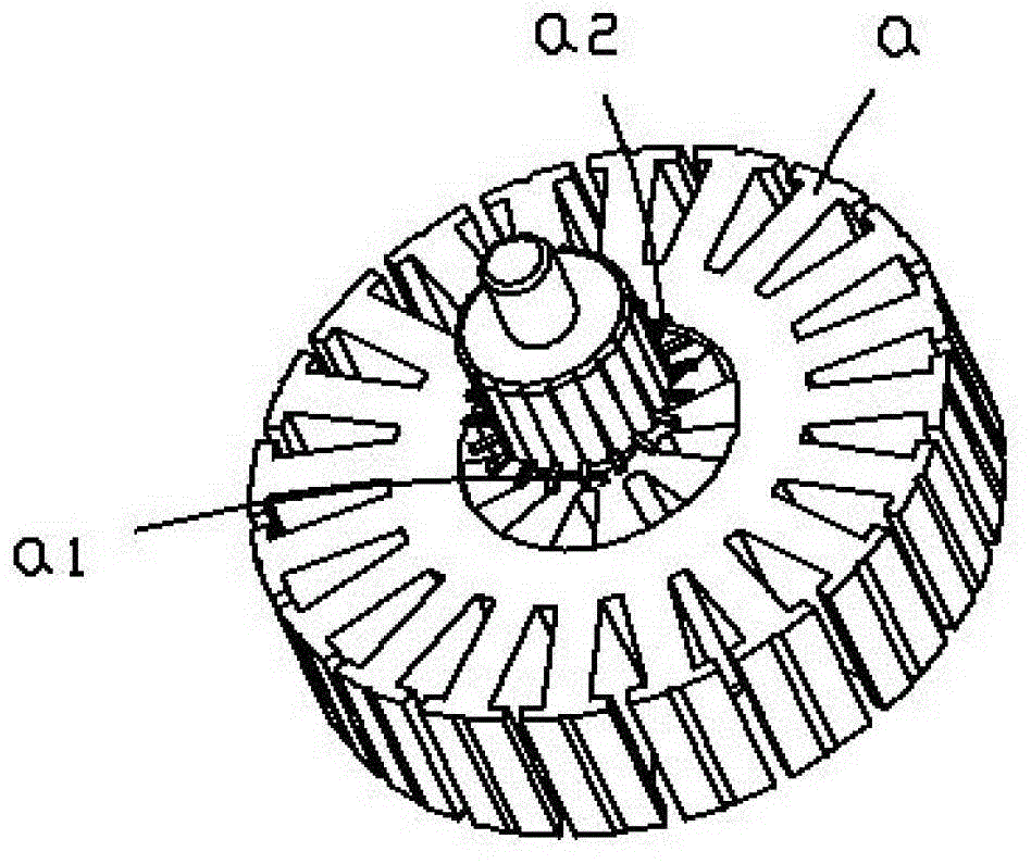
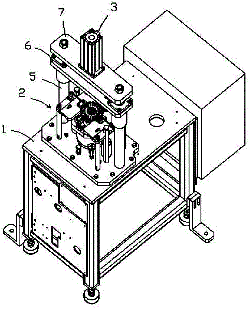
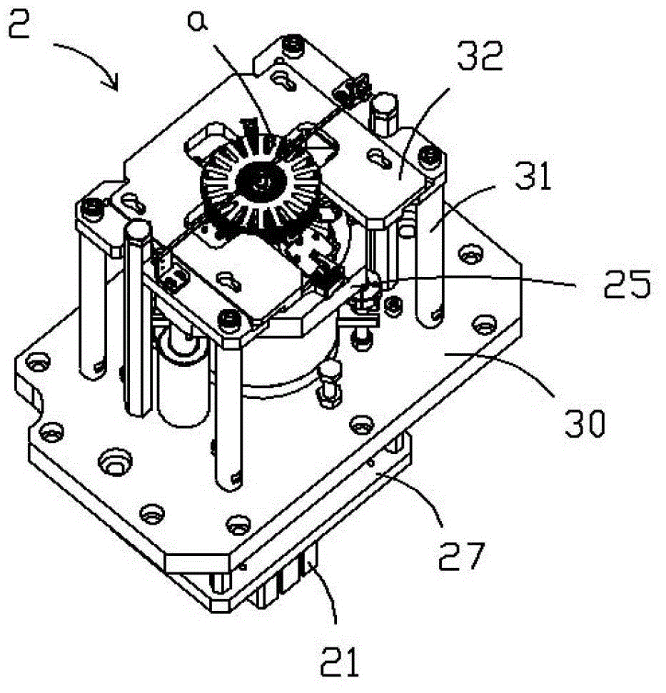
[0021] Such as Figures 2 to 7 Shown is an embodiment of a motor rotor winding shaping machine of the present invention, which includes a frame 1, on which a pressure head 4 that is driven by a first cylinder 3 and can move up and down is located below the pressure head 4 The frame 1 is provided with a cable shaping mechanism 2;

[0022] The structure of the wire shaping mechanism 2 includes an inner core body 25, and the telescopic disk 22 is placed on the inner core body 25. An outer cone surface 251 is formed on the inner core body 25, and an inner cone surface 221 is formed on the telescopic disk 22. The shaping plate 23 is placed on the outer cone surface 251, the rear end of the shaping plate 23 is pressed against the inner cone surface 221, the outer cone surface 251 is provided wi...


PUM


Abstract

The invention discloses a motor rotor winding shaping machine, which comprises a rack, wherein the rack is provided with a pressure head which can move up and down under the driving of a first cylinder, and the rack below the pressure head is provided with a wire shaping mechanism; and the wire shaping mechanism structurally comprises an inner core body, a telescopic disc is sleeved in the inner core body, an outer conical surface is molded on the inner core body, an inner conical surface is molded on the telescopic disc, a shaping plate is arranged on the outer conical surface, the rear end of the shaping plate is pressed against the inner conical surface, the outer conical surface is provided with a notch, a spring is arranged in the notch, one end of spring applies a force to the notch wall, the other end applies a force to the shaping plate, the shaping plate is provided with a gap portion, a front end hook portion of a pressing claw installed on the telescopic disc is arranged in the gap portion, an elastic telescopic rod is installed in a center hole of the inner core body, and the telescopic disc is connected with a piston rod of a second cylinder. The motor rotor winding shaping machine disclosed by the invention can reduce the production cost greatly, and improve the production efficiency.

Description

Technical field: [0001] The invention relates to the technical field of motor rotor processing equipment, in particular to a motor rotor winding shaping machine. Background technique: [0002] Such as figure 1 Shown is a schematic diagram of the structure of a motor rotor. In the figure, a winding foot a2 is formed on the motor rotor a. During processing, wires need to be wound on the motor rotor a, and the wire will be wound on the winding foot a2. After the winding is completed, there will be a number of crossed wires at the position a1 shown in the figure. These wires are in a loose state, and some wires may even protrude outwards, so this part of the wires needs to be processed. To make it tensioned, there are two ways to deal with this loose winding in the prior art. One is manual, and then it is completed with the help of some simple tools. This processing method has relatively low production efficiency, which will make the processing of the The labor cost of the mot...

Claims


Application Information

Patent Timeline
Patent Type & Authority Patents(China)
IPC IPC(8): H02K15/00
Inventor 陆辉
Owner XIONG HUA MACHINERY SUZHOU CO LTD
Why Eureka
Try Eureka