
Scanning device and method for use in an automated analyser

an automated analysis and scanning device technology, applied in the direction of instruments, mountings, sensing record carriers, etc., can solve the problems of complex mechanics, inability to focus on objects located in different distances, and inability to reflect embers

Active Publication Date: 2021-04-06
STRATEC BIOMEDICAL AG
View PDF14 Cites 0 Cited by
  • Summary
  • Abstract
  • Description
  • Claims
  • Application Information

AI Technical Summary

Benefits of technology

The invention allows for a device and scanning method with simple mechanics and a wide range of functions to be used in an automated analyzer. This improves the efficiency and flexibility of the system.

Problems solved by technology

It is a disadvantage of the disclosed device that the reflecting ember can omly be orientated to one side and has to be turned for reading bar codes on the opposite side.
A further disadvantage is that the distance between reflecting member and bar code reader is fixed so that focusing to objects located in different distances will not be possible.
The disadvantages of the prior art using two drives are the complex mechanics, high maintenance costs, a high risk of default, large space requirement and high costs.
The disadvantage of using a laser scanner on the other hand is the small range of functions limited to the barcode reading function excluding additional functions such as reading of two dimensional codes, cap detection and others.

Method used


Image

  • Scanning device and method for use in an automated analyser
  • Scanning device and method for use in an automated analyser
  • Scanning device and method for use in an automated analyser

Examples


Embodiment Construction

[0039]The technical problem is solved by the independent claims. The dependent claims cover further specific embodiments of the invention.

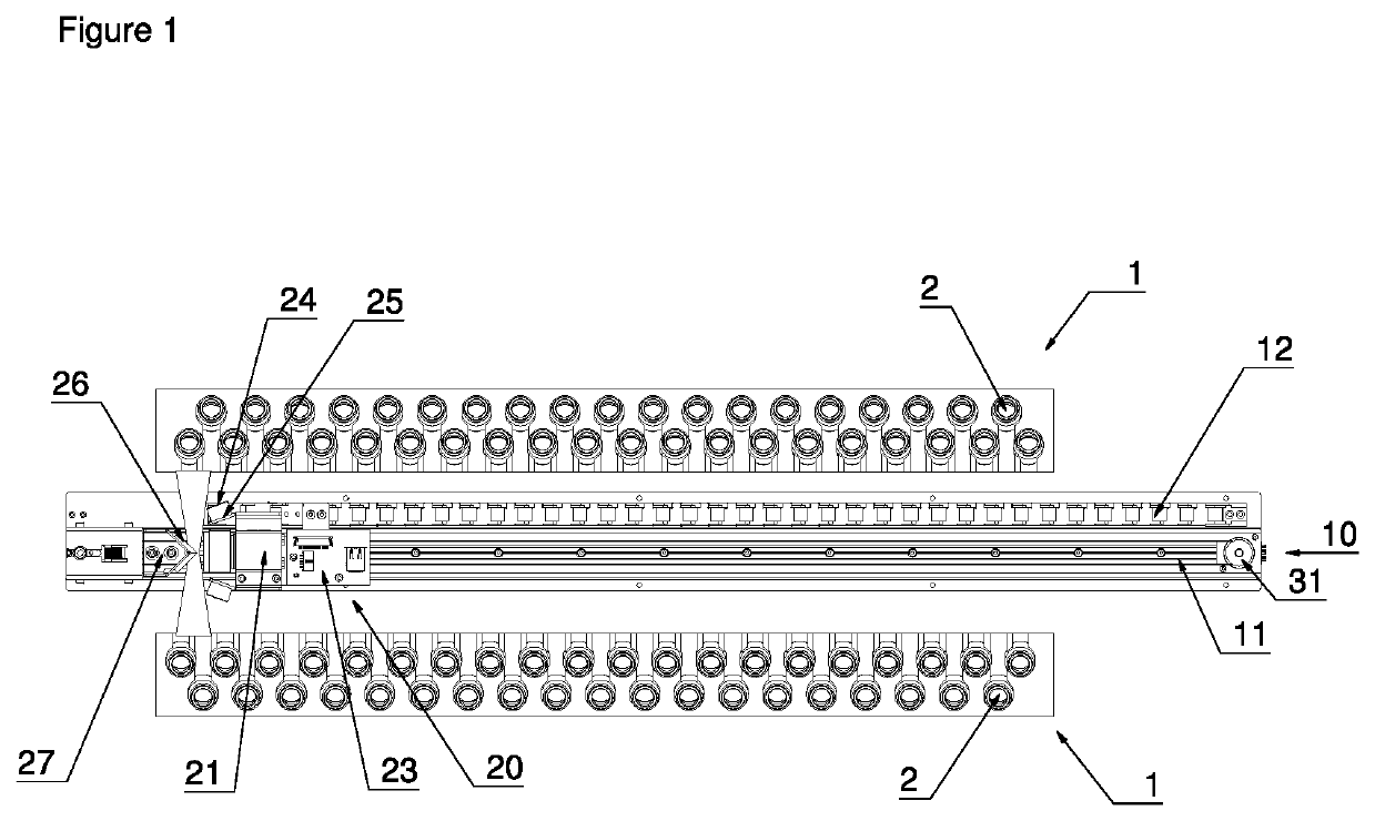
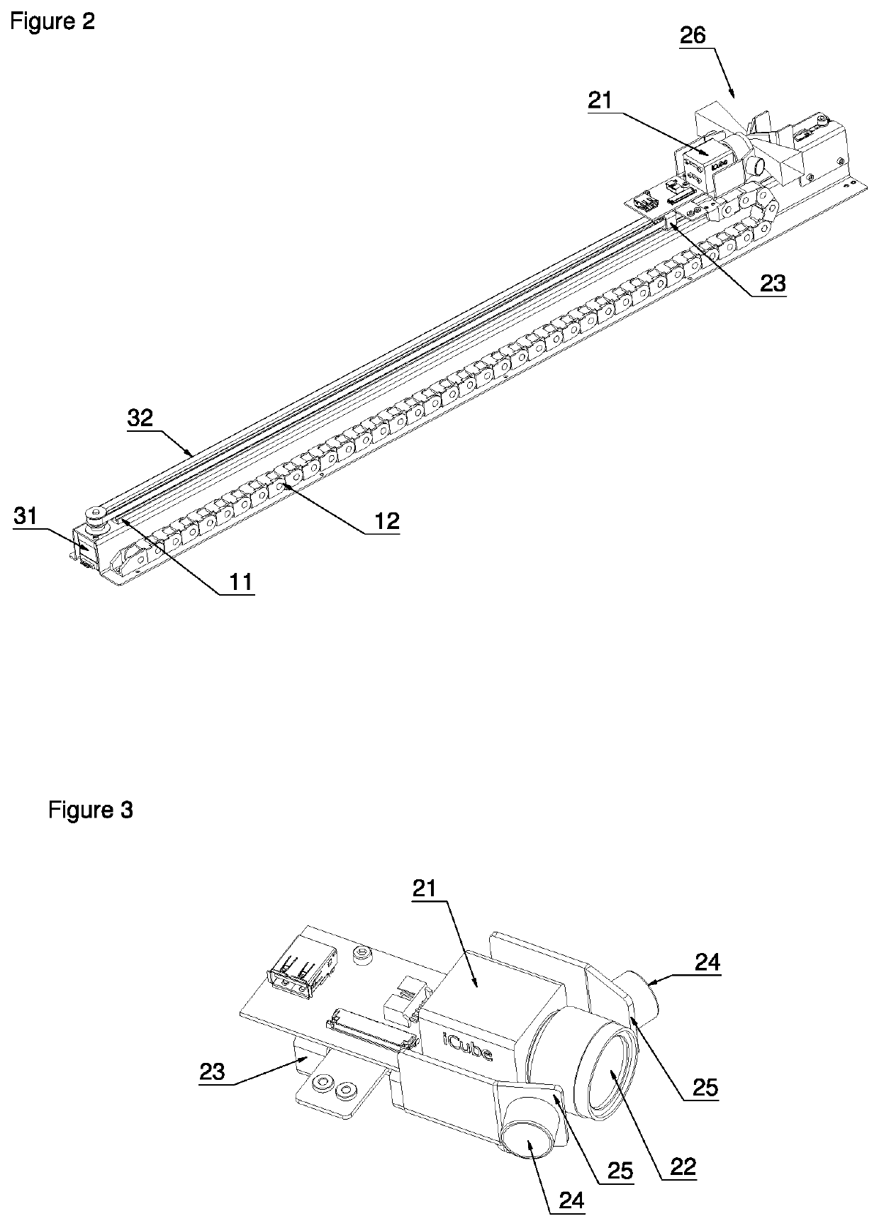
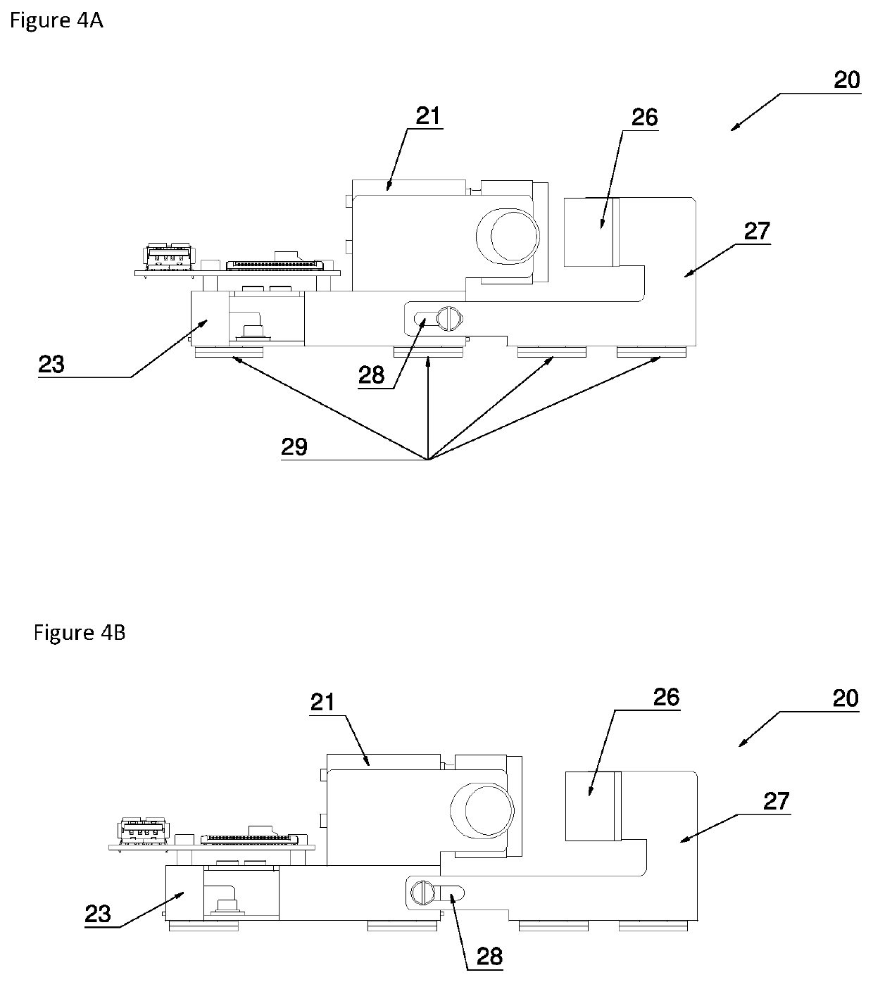
[0040]The invention provides a device and a scanning method for use in an automated analyser, wherein a scanning unit is enabled to move past and in front of an object and set two different focus levels with one and the same drive unit in order to scan objects or codes on objects.

[0041]Objects to be scanned include any receptacle suitable for use in automated analysers and may comprise a lid and / or a code. Codes may be chosen from the group comprising but not limited to one dimensional codes such as bar codes and two dimensional codes as for example QR codes, aztec codes and data matrices. Any code may adhere to the object via a label. Receptacles may be chosen from the group comprising but not limited to containers, tubes and bottles. The objects usually contain a sample and / or a reagent. A sample may be liquid or solid and stem from a patient fo...


PUM

PropertyMeasurementUnit
distanceaaaaaaaaaa
depth of fieldaaaaaaaaaa
distancesaaaaaaaaaa

Abstract

A scanning method with simple mechanics for use in an automated analyser to scan objects or codes on objects. The invention enables one to move a scanning unit comprising a camera and two deflection mirrors and to set two different focus levels with one and the same drive unit.

Description

CROSS-REFERENCE TO RELATED APPLICATIONS[0001]The present application claims priority to British Patent Application No. GB 1715182.0 filed on Sep. 20, 2017. The aforementioned application is hereby incorporated by reference in its entirety.BACKGROUND OF THE INVENTIONField of the Invention[0002]The field of the invention relates to a device and a scanning method for use in an automated analyser to scan objects or codes on objects.Brief Description of the Related Art[0003]Automated analyser systems for use in clinical diagnostics and life sciences are produced by a number of companies. For example, the Stratec Biomedical AG, Birkenfeld, Germany, produces a number of devices for specimen handling and detection for use in automated analyser systems and other laboratory instrumentation.[0004]In clinical diagnostics and life sciences automated analysers are used for tasks such as specimen handling, specimen preparation, detection and analysis. Automated scanning systems are used in automat...

Claims


Application Information

Patent Timeline
Patent Type & Authority Patents(United States)
IPC IPC(8): G06K7/10G01N35/02G01N35/00G06K7/14G02B7/04
CPCG06K7/10722G01N35/00732G01N35/026G06K7/10881G06K7/1413G02B7/04G06K2007/10524B01L9/06G01N35/00584G06K7/10821
Inventor ZVER, MARTINBURKART, MICHAEL
Owner STRATEC BIOMEDICAL AG
Learn More