Sending device and communication system
A technology of sending device and receiving device, which is applied in the direction of transmission system, digital transmission system, electrical components, etc., can solve problems such as inability to improve transmission efficiency, and achieve the effect of efficient communication
- Summary
- Abstract
- Description
- Claims
- Application Information
AI Technical Summary
Problems solved by technology
Method used
Image
Examples
Embodiment approach 1
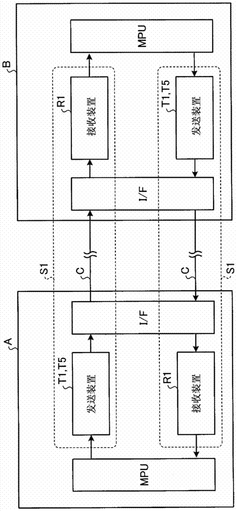
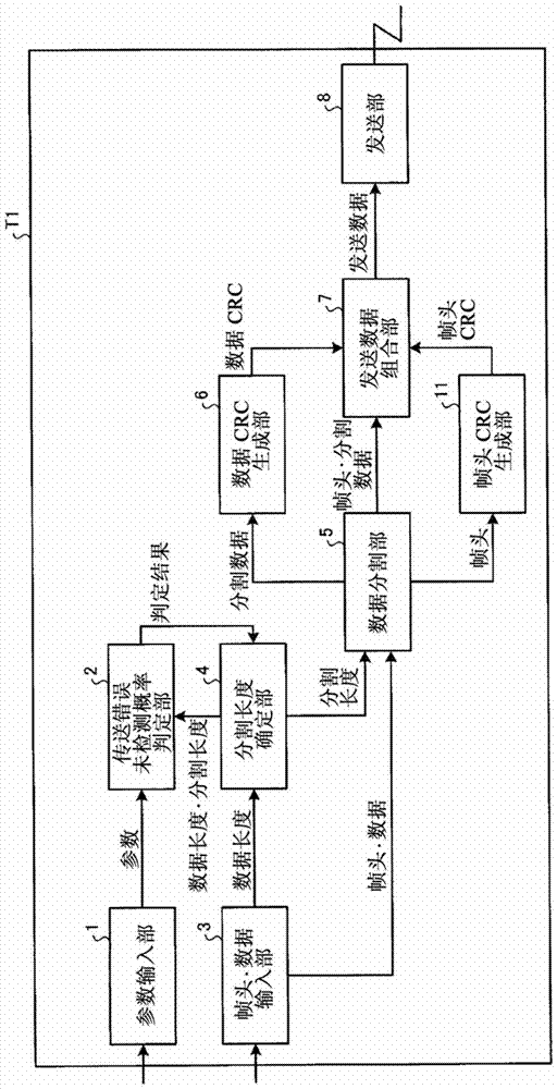
[0064] FIG. 1-1 is a diagram illustrating the configuration of a communication system according to Embodiment 1 of the present invention. The communication system S1 according to Embodiment 1 is configured by connecting a transmission device T1 and a reception device R1 via a communication line C. FIG. In Fig. 1-1, a communication system S1 is constituted by a transmitter T1 mounted on equipment A constituting FA (Factory Automation) and a receiving device R1 mounted on equipment B constituting FA. The transmitting device T1 on the device B and the receiving device R1 mounted on the device A constitute another communication system S1. The equipment A is, for example, a programmable logic controller (PLC) as a control device. The facility B is, for example, a processing device to be controlled.
[0065]A programmable logic controller (PLC) (device A) as a control device has, for example: an MPU (Micro Processing Unit) that controls processing within the programmable logic con...
Embodiment approach 2
[0113] FIG. 2-1 is a diagram illustrating the configuration of a communication system according to Embodiment 2 of the present invention. The communication system S2 according to Embodiment 2 is configured by connecting a transmission device T2 and a reception device R2 via a communication line C. FIG. In Fig. 2-1, a communication system S2 is constituted by the transmitter T2 mounted on the device A constituting the FA and the receiving device R2 mounted on the device B constituting the FA. The device T2 and the receiving device R2 mounted on the device A constitute another communication system S2. In addition, since the device A, the device B, etc. are the same as those in the first embodiment, the description in the first embodiment is referred to, and the description is omitted here.
[0114] FIG. 2-2 is a block diagram illustrating the configuration of the transmission device T2 of the communication system S2 according to the second embodiment. The transmitting device T...
Embodiment approach 3
[0155] FIG. 3-1 is a diagram illustrating the configuration of a communication system according to Embodiment 3 of the present invention. The communication system S3 according to Embodiment 3 is configured by connecting a transmission device T3 and a reception device R3 via a communication line C. FIG. In Fig. 3-1, a communication system S3 is constituted by the transmitter T3 mounted on the device A constituting the FA and the receiving device R3 mounted on the device B constituting the FA. The device T3 and the receiving device R3 mounted on the device A constitute another communication system S3. In addition, since the device A, the device B, etc. are the same as those in the first embodiment, the description in the first embodiment is referred to, and the description is omitted here.
[0156] FIG. 3-2 is a block diagram illustrating the configuration of the transmission device T3 of the communication system S3 according to the third embodiment. The transmitting device T3...
PUM
 Abstract
Description
Claims
Application Information
 - R&D
- Intellectual Property
- Life Sciences
- Materials
- Tech Scout
- Unparalleled Data Quality
- Higher Quality Content
- 60% Fewer Hallucinations
Browse by: Latest US Patents, China's latest patents, Technical Efficacy Thesaurus, Application Domain, Technology Topic, Popular Technical Reports.
© 2025 PatSnap. All rights reserved.Legal|Privacy policy|Modern Slavery Act Transparency Statement|Sitemap|About US| Contact US: help@patsnap.com


