Supercharge Your Innovation With Domain-Expert AI Agents!

Treatment liquid flow rate meter

A technology for processing liquids and flowmeters. It is applied in liquid/fluid solids measurement, flow measurement/mass flow measurement, and measurement devices, etc., and can solve the problems of complicated and easy-to-change complicated supply piping and its surroundings.

Inactive Publication Date: 2013-11-20
TOKYO ELECTRON LTD +1
View PDF7 Cites 1 Cited by
  • Summary
  • Abstract
  • Description
  • Claims
  • Application Information

AI Technical Summary

Problems solved by technology

[0004] However, if an air bubble detection unit different from a velocity meter or a flow meter, etc. is provided on the supply pipe, there is a problem that the configuration of the supply pipe and its surroundings becomes complicated.
In addition, there is a problem that the maintenance (maintenance) work is also likely to become complicated, and also leads to a large-scale

Method used


Image

  • Treatment liquid flow rate meter
  • Treatment liquid flow rate meter
  • Treatment liquid flow rate meter

Examples


Embodiment Construction

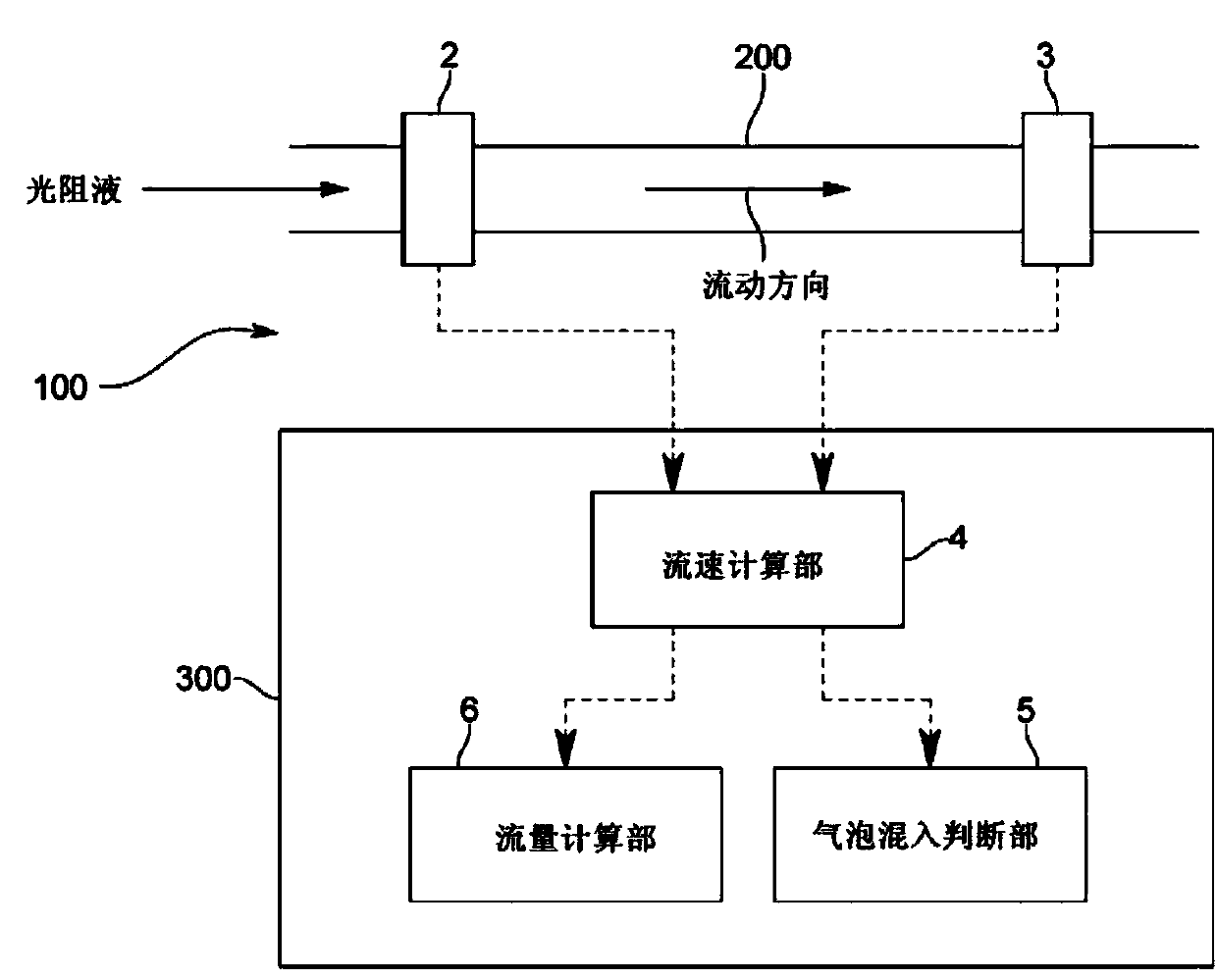
[0032] The process liquid flow meter 100 of this embodiment measures the flow velocity and flow rate of the photoresist liquid flowing in a supply pipe 200 including, for example, a fluorinated polyacrylate (PFA) tube (tube). It is connected to a photoresist coating device of an unillustrated semiconductor manufacturing device. In addition, since the supply piping 200 is constituted by a PFA pipe, there is no pressure loss such as a throttle valve, so air bubbles are less likely to be generated.

[0033] Specifically, as figure 1 As shown, the flowmeter 100 for processing liquid includes: a pair of ultrasonic vibrators 2, 3 arranged at a fixed distance apart in the flow direction of the supply pipe; The detection signals obtained by the sonic vibrators 2 and 3 calculate the flow velocity of the photoresist liquid; the bubble mixing judging part 5 judges whether bubbles are mixed in the photoresist liquid based on the calculated time variation of the flow velocity of the photo...


PUM


Abstract

Provided is a treatment liquid flow rate meter which is provided with a variety of functions and is easy to use, specifically a treatment liquid flow rate meter which measures the flow rate of treatment liquid flowing through a supply pipe (200) and comprises: a pair of ultrasonic vibrators (2, 3) arranged separated by a fixed distance in the direction of flow of the supply pipe (200); a flow rate calculation section (4) for calculating the flow rate of the treatment liquid based on a first arrival time (T1), which is the time an ultrasonic wave emitted from the first ultrasonic vibrator (2) arrives at the second ultrasonic vibrator (3), and a second arrival time (T2), which is the time an ultrasonic wave emitted from the second ultrasonic vibrator (3) arrives at the first ultrasonic vibrator (2); and a bubble ingress determination section (5) for determining whether or not bubbles are mixed in with the treatment liquid, based on the amount of temporal change in the calculated treatment liquid flow rate.

Description

technical field [0001] The present invention relates to a flowmeter for processing liquid preferably used for processing liquid such as photoresist liquid. Background technique [0002] A photoresist coating device in a semiconductor manufacturing device uniformly coats a very thin photoresist on a wafer, thereby making the wafer photosensitive. Here, whenever the photoresist is uniformly coated on the wafer, if bubbles are contained in the photoresist liquid, there is a problem that coating unevenness occurs and uniform coating cannot be performed. [0003] Therefore, conventionally, as shown in Patent Document 1, there has been a device configured as follows. This device is provided with a bubble detection unit on the supply pipe, whereby the presence or absence of bubbles in the photoresist liquid can be automatically detected. The supply pipe supplies the photoresist liquid to the photoresist device. Furthermore, in order to apply the resist uniformly, a flow meter for...

Claims


Application Information

Patent Timeline
Patent Type & Authority Applications(China)
IPC IPC(8): G01F1/66G01N29/02H01L21/027
CPCG01F1/66G01F1/74G01F1/667G01F1/663G01N29/02
Inventor 佐藤尊三安藤了至内村幸治
Owner TOKYO ELECTRON LTD
Features
  • R&D
  • Intellectual Property
  • Life Sciences
  • Materials
  • Tech Scout
  • Unparalleled Data Quality
  • Higher Quality Content
  • 60% Fewer Hallucinations
Learn More