
Workpiece chuck

A technology for chucks and workpieces, applied in the field of workpiece chucks, can solve problems such as poor positional accuracy, poor clamping stability, and unguaranteed workpiece positional accuracy, and achieve low error, fast and accurate opening and clamping, and good The effect of synchronicity

Inactive Publication Date: 2013-11-27
WUJIANG LILI JIANXING CASTING FACTORY
View PDF6 Cites 6 Cited by
  • Summary
  • Abstract
  • Description
  • Claims
  • Application Information

AI Technical Summary

Problems solved by technology

[0002] Traditional drilling machines and horizontal milling machines use bench vises to fasten workpieces, but this clamping method has poor positional accuracy and poor clamping stability, while traditional three-jaw chucks The screw clamping, after a long time of use, the position of the workpiece after clamping can not be guaranteed

Method used


Image

  • Workpiece chuck
  • Workpiece chuck
  • Workpiece chuck

Examples


Embodiment Construction

[0018] Further description will be given below in conjunction with the accompanying drawings

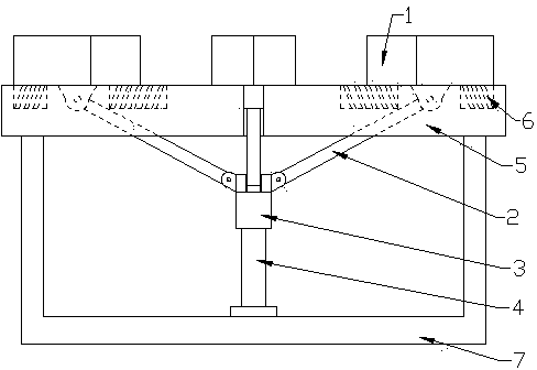
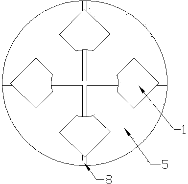
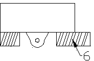
[0019] like Figure 1~4 As shown, a workpiece chuck includes several clamping jaws 1, guide rails 8 having the same number as clamping jaws 1, and a chuck body 5. The guide rails 8 are arranged in an array pointing to the center of the chuck body 5, and the clamping The claw 1 is installed in the chuck body 5 through the guide rail 8, and the chuck also includes a connecting rod seat 3, a telescoping device 4, a connecting rod 2 having the same number as the clamping claw 1, one end of the connecting rod 2 and the clamping claw The bottom of 1 is rotatably connected, the other end of connecting rod 2 is rotatably connected to connecting rod seat 3, and said connecting rod seat 3 is suspended on the bottom of the chuck, said connecting rod seat 3 is connected to one end of telescopic device 4, and said telescopic device 4 The actuating direction is perpendicular to the plane of the c...


PUM


Abstract

The invention discloses a workpiece chuck. Clamping claws on the chunk move synchronously through an umbrella structure composed of connecting rods and a telescopic device. Compared with a traditional chunk with a spiral clamping mode, the workpiece chuck has fewer errors and better synchronization, and clamping force can be adjusted very conveniently through adjustment on the telescopic device. Compared with a traditional rotating type clamping mode, the workpiece chuck is more rapid and accurate in opening and clamping.

Description

technical field [0001] The invention relates to a workpiece chuck, which belongs to the field of mechanical processing. Background technique [0002] Traditional drilling machines and horizontal milling machines use bench vises to fasten workpieces, but this clamping method has poor positional accuracy and poor clamping stability, while traditional three-jaw chucks After a long time of use, the position of the workpiece after clamping cannot be guaranteed. Contents of the invention [0003] The purpose of the present invention is to provide a technical solution that can solve the above problems. [0004] The present invention is realized by following method: [0005] A workpiece chuck, comprising several clamping claws, guide rails with the same number as the clamping claws, and a chuck body, the guide rails are arranged in an array pointing to the center of the chuck body, and the clamping claws are installed into the chuck body through the guide rails , the chuck also...

Claims


Application Information

Patent Timeline
IPC IPC(8): B23B31/12
Inventor 谈建兴
Owner WUJIANG LILI JIANXING CASTING FACTORY
Learn More