Ultrasonic machining method and device for groove sides

A processing device and processing method technology, applied in the field of ultrasonic processing and groove side ultrasonic processing, can solve the problems of low processing efficiency, poor effect, inflexible rotation of the cutter head 2, etc., and achieve good processing effect, simple and reliable operation

Active Publication Date: 2013-11-27
赵显华
View PDF6 Cites 7 Cited by
  • Summary
  • Abstract
  • Description
  • Claims
  • Application Information

AI Technical Summary

Problems solved by technology

The structure of the ultrasonic cutter head can design the size of the cutter head to be smaller, and can perform ultrasonic processing on the smaller grooves on the metal workpiece 1, but the direction of the ultrasonic energy output is inconsistent with the direction of the

Method used


Image

  • Ultrasonic machining method and device for groove sides
  • Ultrasonic machining method and device for groove sides
  • Ultrasonic machining method and device for groove sides

Examples


Example Embodiment

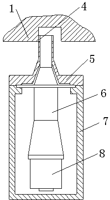
[0021] Such as image 3 As shown, the groove side ultrasonic processing device of the present invention includes a tool head 4, a bending vibration horn 6, a bending vibration transducer 8 and a housing 7. The bending vibration transducer 8 is installed in the housing 7. The flexural vibration horn 6 is mounted on the housing 7 through the support body 5, one end of the flexural vibration horn 6 is connected to the flexural vibration transducer 8, and the other end extends out of the housing 7. The tool head 4 can be directly set on the bending vibration horn 6, including directly fixed on the bending vibration horn 6, or processing mounting holes on the bending vibration horn 6, so that the tool head 4 can be movably installed in the bending vibration Horn 6 on. To make the processing effect better, the tool head 4 is set at the maximum amplitude of the bending vibration horn 6. The tool head 4 may also be arranged on the support body 5 and contact with the bending vibration...


PUM


Abstract

Disclosed is an ultrasonic machining method and device for groove sides. The method comprises that a bending vibration transducer is used for enabling a variable-amplitude pole to produce bending vibration, a tool head is arranged on the variable-amplitude pole, the variable-amplitude pole and the tool head extend into a groove on a metal workpiece, the variable-amplitude pole produces the bending vibration under the action of the bending vibration transducer and drives the tool head to perform high-frequency vibration on the groove sides, the tool head moves relative to the groove sides, and ultrasonic machining of the groove sides is finished. The device comprises the tool head, the bending vibration variable-amplitude pole, the bending vibration transducer and a casing. According to the method and the device, longitudinal vibration of existing groove sides during ultrasonic machining is changed, the bending vibration transducer is used for enabling the variable-amplitude pole to produce bending vibration, and vibration for the narrow groove sides is located at the position of the maximum amplitude, so that phenomena that longitudinal vibration variable-amplitude poles and ultrasonic metal surface machining cutters can not be used for machining the narrow groove sides are avoided, the operation is simple and reliable, and the machining effect is good.

Description

technical field [0001] The invention relates to a method and device for ultrasonically processing the side of a groove on a metal workpiece, and belongs to the technical field of ultrasonic processing of the groove side. Background technique [0002] Ultrasonic has been widely used in the surface processing of metal workpieces to reduce the roughness value of the workpiece surface. Ultrasonic processing on the surface of metal workpieces is usually completed by an ultrasonic processing device installed on the machine tool, and the ultrasonic processing device is connected to the ultrasonic generator through wires. Such as the "ultrasonic metal surface processing device" disclosed in Chinese patent document CN1690231, the device includes an ultrasonic generator and an ultrasonic processing device, and the ultrasonic processing device includes a casing, a piezoelectric ceramic transducer, a half-wavelength compound horn and a tool head, The piezoelectric ceramic transducer is...

Claims


Application Information

Patent Timeline
IPC IPC(8): B23P9/04
Inventor 赵显华
Owner 赵显华
Why Eureka
Try Eureka