Universal hydraulic tool for framework machining

A hydraulic and frame technology, applied in metal processing equipment, metal processing machinery parts, positioning devices, etc., can solve problems such as low processing accuracy, inconsistent deformation state, and large human influence factors, so as to improve clamping efficiency and clamping Stable and reliable effect

Active Publication Date: 2013-11-27
CRRC NANJING PUZHEN CO LTD
View PDF7 Cites 10 Cited by
  • Summary
  • Abstract
  • Description
  • Claims
  • Application Information

AI Technical Summary

Problems solved by technology

At present, the design and manufacture of processing tooling is mainly carried out according to the characteristics of the product, which lacks versatility, and the clamping form between the tooling and the frame is all manually operated, and there is no standard for the control of the clamping force, and the human factors are relatively large. , it is easy to cause the deformation of the processing and clamping, and the deformation state is inconsistent, which also brings certain difficulties to the subsequent analysis
[0003] After searching, it was found that the Chinese utility model patent with application number: 200920103536.0 introduced a general-purpose processing tool for the side wall and bottom plate of high-speed EMUs. Although this structure can realize the clamping process of the side wall and the floor, because of the complex structure, the processing accuracy is low. , due to structural limitations, it cannot meet the clamping needs of different departments, and the processing efficiency is not high

Method used


Image

  • Universal hydraulic tool for framework machining
  • Universal hydraulic tool for framework machining

Examples


Embodiment 1

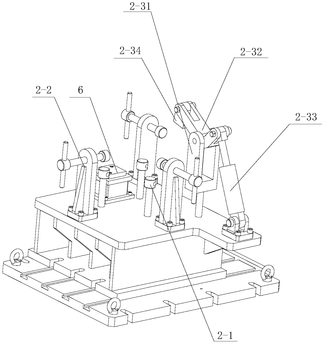
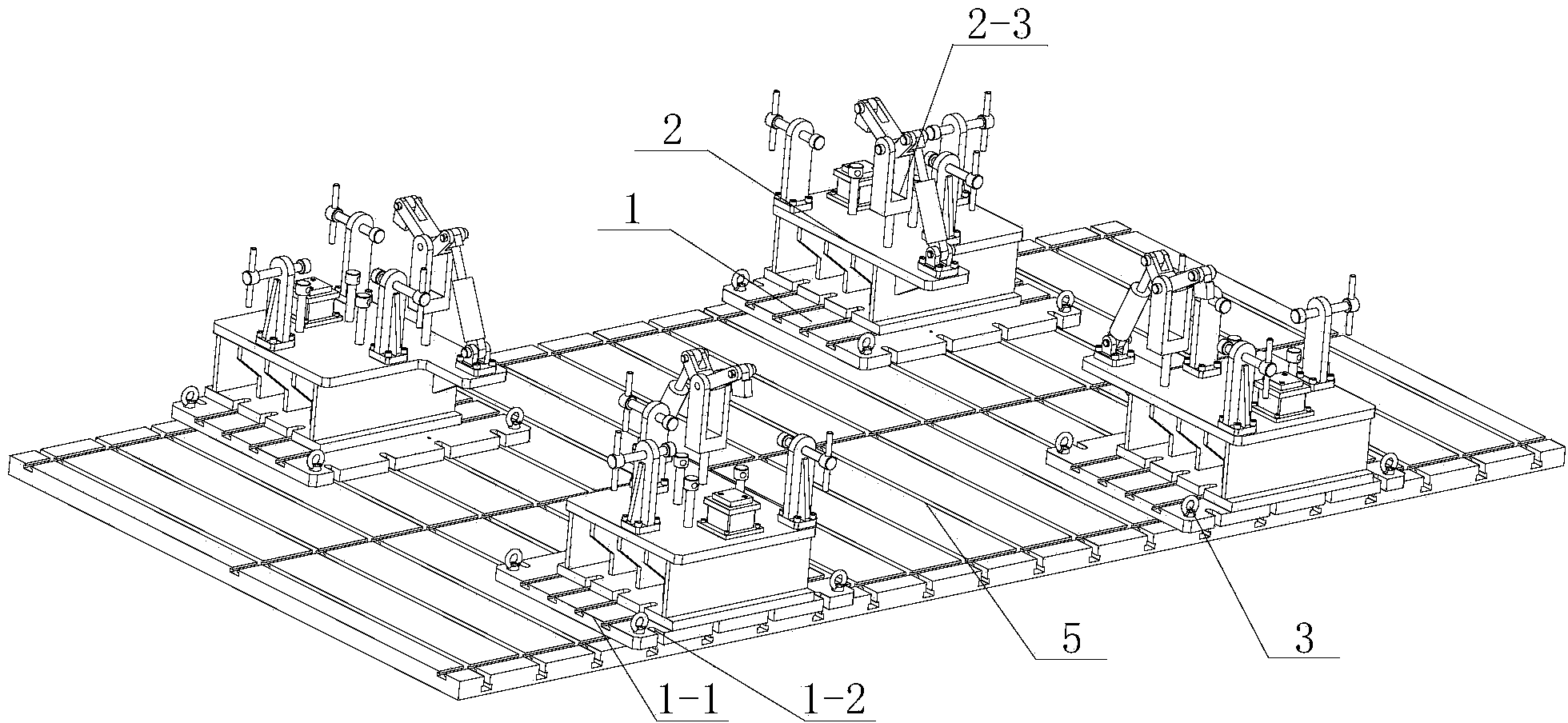
[0014] A general hydraulic tooling for frame processing provided in this embodiment, the structure is as follows figure 1 with figure 2 As shown, it includes a workbench 5, a workbench connection module 1 and four tooling modules 2 installed on the workbench connection module 1. The four corners of the workbench connection module are fixedly installed with hoisting rings 3, and the upper surface of the workbench connection module has Y To the I-shaped groove 1-1, there is a vertical U-shaped groove 1-2 at the X-direction side edges of the workbench connection module. The tooling module includes a positioning device 2-1, an adjusting device 2-2 and Clamping device 2-3, the positioning device is composed of Z-direction positioning surface, Y-direction positioning surface and X-direction positioning surface. The Z-direction positioning surface, Y-direction positioning surface and X-direction positioning surface are all composed of adjusting nuts; The Y-direction adjusting bolt ...


PUM


Abstract

The invention relates to a universal hydraulic tool for shaft bracket machining, and belongs to the technical field of machining equipment. The universal hydraulic tool structurally comprises workbench connecting modules and at least four tool modules arranged on the workbench connecting modules, Y-direction H-shaped grooves are formed in the upper surfaces of the workbench connecting modules, the tool modules comprise locating devices, adjusting devices and clamping devices, the locating devices, the adjusting devices and the clamping devices are arranged on tool supports, and the locating devices are composed of Z-direction locating faces, Y-direction locating faces and X-direction locating faces. The adjusting devices are composed of Y-direction adjusting bolts and X-direction adjusting bolts. The middle portions of the clamping force arms of the clamping devices are movably arranged at the top ends of clamping supports through pin shafts, one ends of the clamping force arms are connected with hydraulic oil cylinders arranged on the tool supports, and clamping press blocks are movably arranged at the other ends of the clamping force arms. The universal hydraulic tool can reduce the investment of new projects in tool machining and lower production cost, meanwhile, a hydraulic system is adopted to clamp machined workpieces, the stability and the reliability of clamping force are ensured, and workpiece clamping efficiency is improved.

Description

technical field [0001] The invention relates to a general hydraulic tool for frame processing, which belongs to the technical field of mechanical processing equipment. Background technique [0002] Frame processing is an essential process in the frame manufacturing process, and processing tooling is one of the most important process equipment in frame processing except for processing equipment. At present, the design and manufacture of processing tooling is mainly carried out according to the characteristics of the product, which lacks versatility, and the clamping form between the tooling and the frame is all manually operated, and there is no standard for the control of the clamping force, and the human factors are relatively large. , it is easy to cause the deformation of the processing and clamping, and the deformation state is inconsistent, which also brings certain difficulties to the subsequent analysis. [0003] After searching, it was found that the Chinese utility...

Claims


Application Information

Patent Timeline
Patent Type & Authority Applications(China)
IPC IPC(8): B23Q3/08
Inventor 鲍凯裴龙洋陆爰汤志钧汪海华王超柴柱谢莹莹宋玉奇金伟方孝钟
Owner CRRC NANJING PUZHEN CO LTD
Why Eureka
Try Eureka