Supercharge Your Innovation With Domain-Expert AI Agents!

Miniature dehydrator

A dehydrator and micro technology, applied in the field of mechanical equipment, can solve the problems of unreasonable structure, large floor space and inconvenient maintenance of dehydrator, and achieve the effect of compact structure, small floor space and convenient maintenance.

Inactive Publication Date: 2013-11-27
江苏美星大地环保科技有限公司
View PDF3 Cites 1 Cited by
  • Summary
  • Abstract
  • Description
  • Claims
  • Application Information

AI Technical Summary

Problems solved by technology

[0003] The technical problem to be solved by the present invention is: aiming at the disadvantages of the existing dehydrator, such as unreasonable structure, large floor space, high cost, heavy body, and inconvenient maintenance, a dehydrator with small shape, low cost, light body, Rationalized micro dehydrator

Method used


Image

  • Miniature dehydrator
  • Miniature dehydrator
  • Miniature dehydrator

Examples


Embodiment Construction

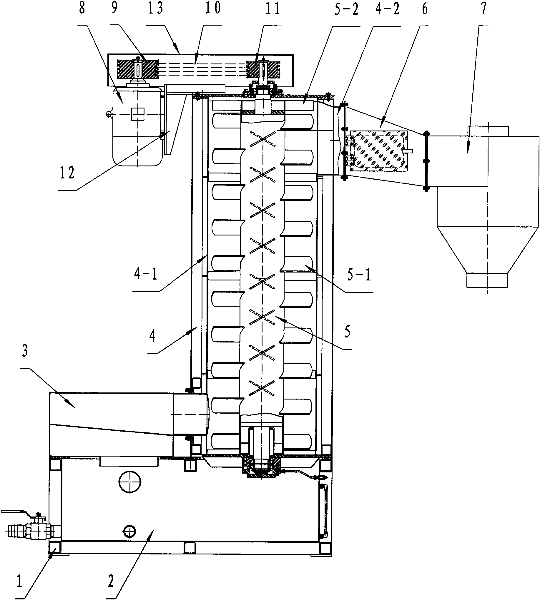
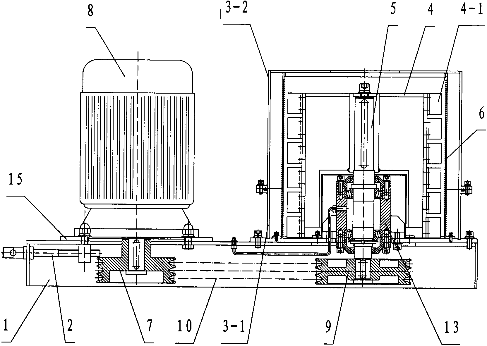
[0013] exist figure 2 Among them, a motor (8) and a cylinder (3) are installed on the base (1), and the cylinder (3) is divided into a lower cylinder fixing seat (3-1) and an upper cylinder (3-2), and the lower cylinder The fixed base (3-1) is fixed on the base (1) with bolts, and the upper cylinder (3-2) is connected with the lower cylinder fixed base (3-1) with bolts. The bottom of the mesh plate (6) is fixedly connected with the lower cylinder fixing seat (3-1) with bolts. The blades (4-1) are L-shaped and fixed to the rotating body (4) with bolts, and the blades (4-1) are arranged in a spiral shape on the rotating body (4). The rotating shaft (5) passes through the center of the rotating body (4), and its upper end is fixed with bolts. A rectangular hole is opened on the side of the mesh plate (6), and one end of the discharge port (11) is facing the square hole, and the other end is exposed outside the device. The lower cylinder holder (3-1) has a square aperture, whi...


PUM


Abstract

The invention discloses a light-weight miniature dehydrator. A cylinder body of the miniature dehydrator is divided into an upper cylinder body and a lower cylinder body; the lower cylinder body is fixed on a base; the upper cylinder body is connected with the lower cylinder body through a bolt; blades are spirally distributed downwards on a rotating body; a rotary shaft penetrates through the center of the rotating body; the upper end of the rotary shaft is fixed through the bolt; a tensioning mechanism is fixedly connected to the base and is connected with a base plate of a motor plate.

Description

technical field [0001] The invention relates to a dehydration device, in particular to a separation device used in the recycling and granulation industry of PE, PP and PS, and belongs to the field of mechanical equipment. Background technique [0002] The structural forms of the known domestic dehydrator are: base (1), cooling water tank (2), feed hopper (3), box body (4), mesh plate (4-1), discharge port (4 -2), rotating shaft (5), blade (5-1), beating plate (5-2), connecting body (6), cyclone outlet (7), motor (8), pulley A (9) , V-belt (10), belt pulley B (11), motor support seat (12), casing (13) are connected successively and form. A box body (4) and a feed hopper (3) are arranged on the base (1), and the cooling water tank (2) is integrated with the base (1). A circular feeding opening is opened directly below the casing (4), and the feeding hopper (3) is connected with the feeding opening with screws. The mesh plate (4-1) is fixed in sections, and is connected with...

Claims


Application Information

Patent Timeline
Patent Type & Authority Applications(China)
IPC IPC(8): B29B13/06B29B17/00B29B9/00
CPCY02W30/62
Inventor 吴恒毅施华军陆张峰练庆余束芳浩黄振华
Owner 江苏美星大地环保科技有限公司
Features
  • R&D
  • Intellectual Property
  • Life Sciences
  • Materials
  • Tech Scout
  • Unparalleled Data Quality
  • Higher Quality Content
  • 60% Fewer Hallucinations
Learn More