Dynamic sealing device for expansion pipe
A dynamic sealing and practical technology, applied in sealing/isolation, wellbore/well parts, earthwork drilling and production, etc., can solve the problems of construction failure, hindering the smooth progress of expansion, prone to jamming, etc., and achieve the effect of keeping clean
- Summary
- Abstract
- Description
- Claims
- Application Information
AI Technical Summary
Problems solved by technology
Method used
Image
Examples
Embodiment 1
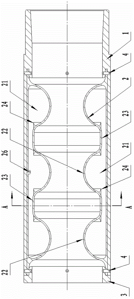
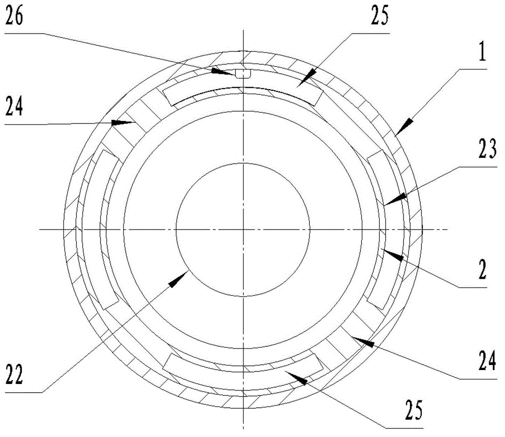
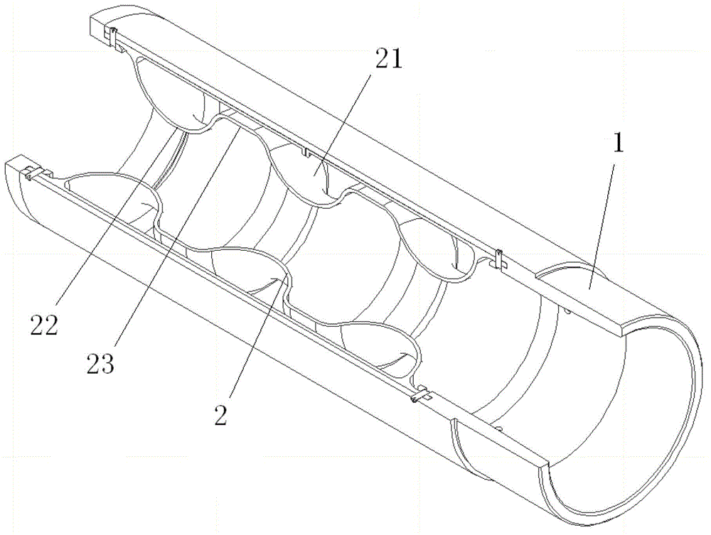
[0033] The dynamic sealing device for the expansion pipe according to the present invention will be described in detail below in conjunction with the accompanying drawings. A dynamic sealing device for an expansion tube, comprising a cylindrical connecting jacket 1, a cylindrical sealing rubber core 2 is fixedly connected inside the connecting jacket 1, the outer wall of the sealing rubber core 2 is sealed and connected with the inner wall of the connecting jacket 1, and the sealing rubber The core 2 is provided with a cavity 21 for inflation, such as figure 1 , figure 2 , image 3 shown.
[0034] The cylindrical sealing rubber core in the dynamic sealing device for the expansion pipe can tightly hug the pressure oil pipe after inflating, and realize the dynamic seal with the pressure oil pipe, so that the dynamic sealing device 61 for the expansion pipe can prevent foreign matter in the well from entering the expansion pipe 65, keep the annulus between the expansion pipe ...
Embodiment 2
[0048] The difference between this embodiment and Embodiment 1 is that: at the annular groove 23 , a metal ring 5 is fixedly connected to the inner surface of the inner wall of the sealing rubber core 2 .
[0049] In Embodiment 1, in order to prevent the sealing rubber core 2 from moving in the axial direction of the connecting sleeve 1 after the sealing rubber core 2 is inflated, and at the same time ensure that the cavities 21 in the plurality of annular protrusions 22 remain connected, at the position of the annular groove 22 A plurality of connecting pieces 24 are provided, and a gap 25 is provided between two adjacent connecting pieces 24 . Although this arrangement can prevent the annular groove 22 from moving in the axial direction of the connecting sleeve 1 to a certain extent, the annular groove 22 will still move in the axial direction of the connecting sleeve 1 at the position of the gap 25, that is, the position without the connecting piece 24 , so the metal ring 5...
Embodiment 3
[0052] In Embodiment 2, in order to prevent all circumferential parts of the annular groove 22 from moving toward the axis of the outer casing 1 , the inner surface of the inner wall of the sealing rubber core 2 is fixedly connected with a metal ring 5 . However, during use, if the gas pressure in the sealing rubber core 2 is too high, the side wall at the annular groove 22 will tend to separate from the metal ring 5, that is, the metal ring 5 will be easily detached, and the service life will be affected. In order to solve this problem, the outer surface of the inner wall of the sealing rubber core 2 is fixedly connected with a metal ring 5, such as Figure 9 shown. In this way, the annular groove 22 will generate compressive stress on the metal ring 5 , and the metal ring 5 will not be easily separated from the side wall of the annular groove 22 . Preferably, the length of the metal ring 5 in the axial direction of the connecting sleeve 1 is equal to the length of the annul...
PUM
 Abstract
Description
Claims
Application Information
 - R&D
- Intellectual Property
- Life Sciences
- Materials
- Tech Scout
- Unparalleled Data Quality
- Higher Quality Content
- 60% Fewer Hallucinations
Browse by: Latest US Patents, China's latest patents, Technical Efficacy Thesaurus, Application Domain, Technology Topic, Popular Technical Reports.
© 2025 PatSnap. All rights reserved.Legal|Privacy policy|Modern Slavery Act Transparency Statement|Sitemap|About US| Contact US: help@patsnap.com


