
electronic doorbell

An electronic doorbell, doorbell technology, applied in electromagnetic audible signals and other directions, can solve problems such as hidden safety hazards, transmission frequency offset, poor consistency, etc., to achieve the effects of improved versatility, stable frequency, and convenient production and debugging

Inactive Publication Date: 2016-05-04
DONGGUAN JUNWEI ELECTRONICS PROD
View PDF6 Cites 0 Cited by
  • Summary
  • Abstract
  • Description
  • Claims
  • Application Information

AI Technical Summary

Problems solved by technology

Most of the existing wireless electronic doorbell transmitters use LC oscillating circuit to generate RF frequency, and then fine-tune to a fixed frequency through adjustable capacitors. The biggest drawback of this circuit is that the transmission frequency changes with the ambient temperature and time. Offset will occur, and it is easy to exceed the safety requirements of the radio, thus causing potential safety hazards. At the same time, the external environment is easy to affect the transmission frequency of this circuit, and the installation conditions are different. This circuit will also affect its transmission frequency through parasitic capacitance, such as The transmission frequency is different when installed on a metal door and on a wooden door. Even weather changes will affect its transmission frequency and effective distance. In addition, it is inconvenient to manually adjust the adjustable capacitor in production, which makes the consistency of the same product poor

Method used


Image

  • electronic doorbell
  • electronic doorbell
  • electronic doorbell

Examples


Embodiment Construction

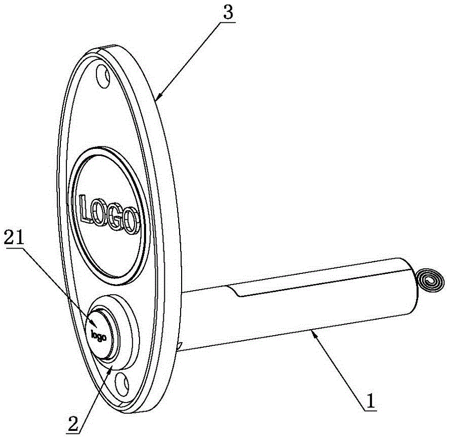
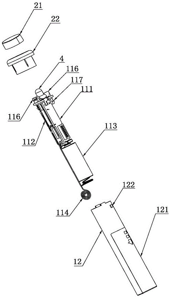
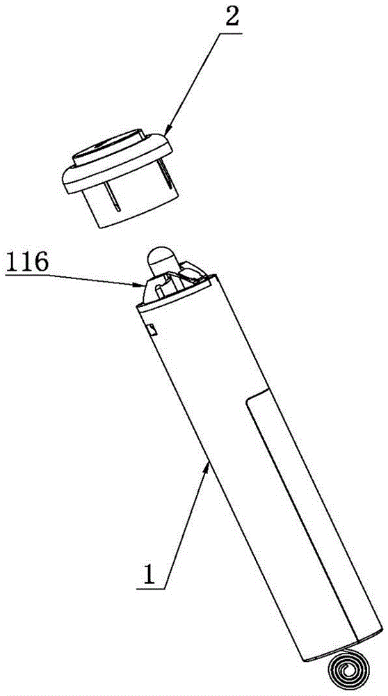
[0028] The present invention will be described in detail below in conjunction with the accompanying drawings and embodiments.

[0029] Such as figure 1 As shown, the electronic doorbell of the present invention includes a button assembly 2 and a control assembly 1 for generating a sounding control signal, and the doorbell also includes a sounding assembly (not shown) connected to the control assembly 1, the The control component 1 is embedded in the wall or inside the door frame and is detachably connected with the button component 2, combined with image 3 and Figure 6 , in the control assembly 1 and the button assembly 2, one assembly is provided with a hook-shaped lock 116, and the other assembly is provided with a connecting block 221 that is engaged with the lock 116, as image 3 As shown, the button assembly 2 and the control assembly 1 are detachably connected through the buckle 116 and the connection block 221 . In this embodiment, the control assembly 1 is provide...


PUM


Abstract

The invention relates to a doorbell, in particular to an electronic doorbell. The electronic doorbell is arranged on a wall or a door frame, and comprises a button component provided with a doorbell button, and a control component used for producing a sound production control signal; the doorbell also comprises a sound production component connected with the control component; the control component can be embedded into the wall or the door frame, and is connected with the button component in a detachable way; the doorbell comprises a doorbell decoration panel arranged on the surface of the wall or the surface of the door frame; the doorbell decoration panel is provided with a through hole; the button component comprises a button shell passing through the through hole; the outer end of the button shell is provided with a convex part used for blocking the doorbell decoration panel. The button component and the control component of the electronic doorbell are connected with each other in the detachable way, so that the universality of the button component and the control component can be greatly improved after interfaces of the button component and the control component are unified; the control component of the electronic doorbell is embedded into the wall or the door frame, the button is left outside, and the doorbell decoration panel can be also arranged for detection, so that the electronic doorbell is in accordance with the whole decoration style of the wall.

Description

technical field [0001] The invention relates to a doorbell, in particular to an electronic doorbell. Background technique [0002] Electronic doorbells include button components that provide doorbell buttons for visitors to press the doorbell and control components that control sound. Electronic doorbells include wired electronic doorbells and wireless electronic doorbells. Wireless electronic doorbells are also called remote doorbells. In the structure of the existing electronic doorbell, the button assembly and the control assembly are designed as a whole and are not clearly separated in an overall structure, so that the button assembly and the control assembly basically do not have universality, that is, the button assembly cannot be combined with other control assemblies. Cooperative use, or the control component cannot be selected to be used in conjunction with other button components. The difference between the wired electronic doorbell and the wireless electronic door...

Claims


Application Information

Patent Timeline
Patent Type & Authority Patents(China)
IPC IPC(8): G08B3/10
Inventor 刘远星
Owner DONGGUAN JUNWEI ELECTRONICS PROD
Learn More