Z-source inverter shunt active power filter and control method thereof

A technology of power filter and control method, which is applied in the direction of active power filter, AC network to reduce harmonic/ripple, single network parallel feeding arrangement, etc., which can solve the problem of deterioration of compensation effect, failure of decoupling, and loss of active power etc. to achieve the effects of reducing control complexity, canceling dead time, and simplifying device protection

Inactive Publication Date: 2015-06-17
HUNAN LINENG TECH +1
View PDF3 Cites 0 Cited by
  • Summary
  • Abstract
  • Description
  • Claims
  • Application Information

AI Technical Summary

Problems solved by technology

In order to prevent the straight-through of the upper and lower bridge arms, the control system must add a dead time when determining the switching state of the switching device, which will inevitably cause the output waveform to deviate from the control target and deteriorate the compensation effect; Fault detection and protection functions increase the complexity of the control system
[0007] (2) The compensation harmonic current output by the existing parallel active electric filter will cause active power fluctuations, and the leakage current of the capacitor bank and the voltage equalizing resistance will also cause a certain amount of active power loss. Therefore, the DC side capacitor voltage control is complicated and must be Adding the active current component to the compensation command current can ensure the stability of the DC side voltage, so that the DC voltage control and the output compensation current control cannot be decoupled; adding the active current to the compensation command current also deteriorates the compensation effect
The constant voltage level of the DC capacitor bank results in less flexibility for shunt active electric filter applications

Method used


Image

  • Z-source inverter shunt active power filter and control method thereof
  • Z-source inverter shunt active power filter and control method thereof
  • Z-source inverter shunt active power filter and control method thereof

Examples


Embodiment Construction

[0034] The invention includes a main circuit composed of a Z-source inverter and a corresponding control circuit.

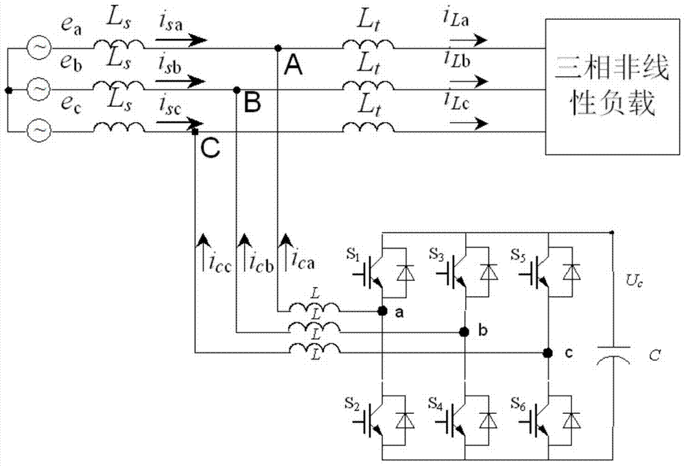
[0035] 1. The main circuit composed of Z source inverter.

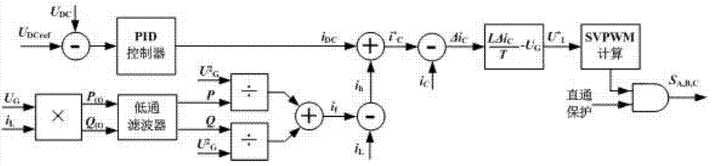
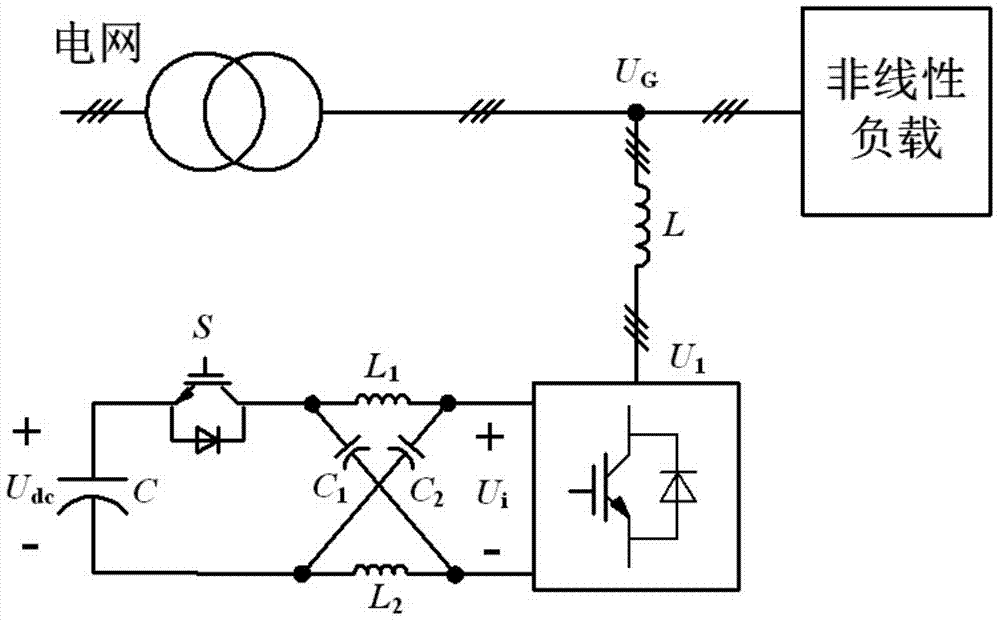
[0036] The main circuit composed of Z source inverter includes power grid, nonlinear load, output inductor, Z source inverter and control circuit; Z source inverter includes DC source, bidirectional switch, Z source network and inverter, DC The source is connected to the inverter through the Z-source network, and a bidirectional switch is connected between the positive end of the DC source and the Z-source network; the control circuit includes a controller, a sensor unit and a power supply unit, and the sensor unit includes a sensor for real-time detection of grid voltage. Voltage sensor, current sensor for real-time detection of nonlinear load current and voltage sensor for real-time detection of DC source voltage, the controller collects the measurement signals of the above sensors, and uses the collec...


PUM


Abstract

The invention discloses a Z-source inverter shunt active power filter and a control method thereof. The Z-source inverter shunt active power filter comprises a power grid, a non-linear load, an output inducer, a Z-source inverter and a control circuit; the Z-source inverter comprises a direct-current source, a bilateral switch, a Z-source network and an inverter, the direct-current source is connected with the inverter through the Z-source network, and the bilateral switch is connected between the anode of the direct-current source and the Z-source network; a control system comprises a controller, a sensor unit and a power unit, the sensor unit comprises a voltage sensor for detecting the voltage of the power grid, a current sensor for detecting the current of the non-linear load, a current sensor for detecting the compensation command current of the inverter and a voltage sensor for detecting the voltage of the direct-current source, and the controller acquires the signals of the sensors, and controls the bilateral switch and the inverter by means of the acquired voltage values and current values. The filter dispenses the dead time in switching signals, and decreases the complexity of control, and the output current waveform is fundamentally not affected by direct-current voltage.

Description

technical field [0001] The invention relates to a Z-source inverter parallel active power filter and a control method thereof. Background technique [0002] Such as figure 1 As shown, the existing parallel active power filter uses a main circuit based on a VSI inverter, and the VSI inverter is connected to the grid through an output filter circuit and impedance inductance, and the DC side is composed of a capacitor bank. [0003] Such as figure 2 As shown, the control circuit of the existing shunt active filter can detect and calculate the harmonic current, reactive current, three-phase unbalance and negative sequence current in the load current in real time, and determine the command to output the compensation current according to the compensation mode value i C * . The DC side capacitor bank mainly plays the role of voltage support in the VSI inverter, and its voltage V C It must be relatively stable, so when the control circuit determines the compensation current...

Claims


Application Information

Patent Timeline
Patent Type & Authority Patents(China)
IPC IPC(8): H02J3/01H02J3/38
CPCY02E40/20
Inventor 胡楷张玘郑小平
Owner HUNAN LINENG TECH
Why Eureka
Try Eureka