Flame detector cooling device and method

A technology for flame detectors and cooling devices, which is applied to household refrigeration devices, combustion methods, and safety devices for combustion chambers. Reduce operating costs, simple and convenient installation and maintenance

Pending Publication Date: 2017-06-13
ELECTRIC POWER SCI RES INST OF GUIZHOU POWER GRID CO LTD
View PDF8 Cites 7 Cited by
  • Summary
  • Abstract
  • Description
  • Claims
  • Application Information

AI Technical Summary

Problems solved by technology

[0003] The technical problem to be solved by the present invention is a flame detector cooling device and method, which changes the flame detection optical fiber sheath tube from a single-layer cooling air duct to a double-layer cooling air duct, so as to solve the problem that the optical fiber is easily damaged and the flame detection probe is easily blocked by dust. And other issues

Method used


Image

  • Flame detector cooling device and method

Examples


Embodiment Construction

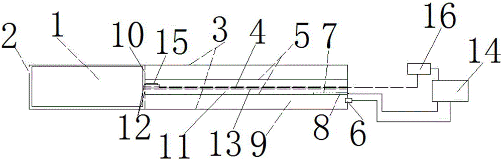
[0026] Preferred embodiments of the present invention will be described in detail below in conjunction with the accompanying drawings.

[0027] see figure 1 As shown, a flame detector cooling device is composed of flame detector probe 1, flame detector probe cooling air outlet 2, outer cooling pipe 3, optical fiber 4, inner cooling pipe 5, outer cooling pipe cooling air inlet 6, inner and outer Cooling pipe ventilation hole slot vent 7, ventilation hole slot 8, outer cooling pipe cooling air duct 9, outer cooling pipe cooling air outlet 10, inner cooling pipe cooling air duct 11, ventilation hole 12, heat insulation layer 13, The air volume adjustment device 14, the temperature measuring element 15 and the regulator 16 are composed. The flame detector probe 1 is set in the outer cooling pipe 3; Connection; the optical fiber 4 is arranged in the inner cooling pipe 5, one end of the optical fiber 4 is connected to the signal output interface of the flame detector probe 1, and t...


PUM


Abstract

The invention discloses a flame detector cooling device which comprises a flame detector probe (1), a cooling air blow-off nozzle (2) of the flame detector probe, an outer cooling tube (3), an optical fiber (4) and an inner cooling tube (5). The flame detector cooling device is characterized in that the flame detector probe (1) is arranged in the outer cooling tube (3); the inner cooling tube (5) is sleeved in the outer cooling tube (3); and the optical fiber (4) is arranged in the inner cooling tube (5), one end of the optical fiber (4) is connected to the flame detector probe (1) while the other end of the optical fiber is connected to an external system, and a flame detecting optical fiber protecting pipe is changed from a single-layered cooling air duct into a double-layered cooling air duct, so that problems that the optical fiber is easy to damage, the flame detecting probe is easy to clog and the like are solved.

Description

technical field [0001] The invention relates to a flame detector cooling device and method, belonging to the technical field of boiler flame detection. Background technique [0002] In the process of thermal power production, the function of the flame detector runs through the whole process from the start of the boiler to the full-load operation, and is used to judge the establishment / extinguishment of the flame in the whole chamber or the unit burner or whether there is fire or no fire, and the equipment is running The reliability and detection accuracy are directly related to the operation safety and stability of the unit. Since the detection system was put into operation, there have been frequent failures such as fiber optic burnout and flame detection probes being blocked by ash, which have seriously threatened the safe and stable operation of the unit. By changing the flame detection optical fiber sheath tube from a single-layer cooling air duct to a double-layer cooli...

Claims


Application Information

Patent Timeline
Patent Type & Authority Applications(China)
IPC IPC(8): F23M11/04F25D1/00
CPCF23M11/045F25D1/00F23M2900/11041
Inventor 安波张锐锋柏毅辉李忠何洪流陈宇黄如云石磐李前敏吴鹏郑有卓
Owner ELECTRIC POWER SCI RES INST OF GUIZHOU POWER GRID CO LTD
Why Eureka
Try Eureka