Stamping die

A technology for stamping dies and shells, applied in forming tools, manufacturing tools, metal processing equipment, etc., can solve the problems of reduced efficiency, inconvenient demoulding process, and low efficiency.

Inactive Publication Date: 2013-12-04
广州市烁烨金属制品有限公司
View PDF6 Cites 7 Cited by
  • Summary
  • Abstract
  • Description
  • Claims
  • Application Information

AI Technical Summary

Problems solved by technology

[0003] The stamping dies of the prior art have the following defects: each time a screw is punched, five steps of mold opening, loading, stamping mold clamping, mold opening, and demoulding need to be carried out separately, and as many screws as needed to be stamped need to be repeated as many times as necessary. The speed is slow and the efficiency is low, and continuous stamping and forming cannot be performed; secondly, because the round bar is placed between the upper mold and the lower mold when discharging, in this way, if the mold opening range is too small before discharging and when the mold is opened, two The distance between the molds is not enough, it is difficult for people to put the round rod in, but if the mold opening range is too large, the stroke of the punch will be increased when the mold is opened and closed, which will consume more time and further reduce the efficiency. There is a certain danger in discharging the material between the two molds. If the punch is accidentally activated, it may hurt the hands; moreover, because the opening of the lower mold is facing upwards, the demoulding process is too inconvenient

Method used


Image

  • Stamping die
  • Stamping die
  • Stamping die

Examples


Embodiment Construction

[0017] The present invention will be further described below in conjunction with the accompanying drawings and specific embodiments.

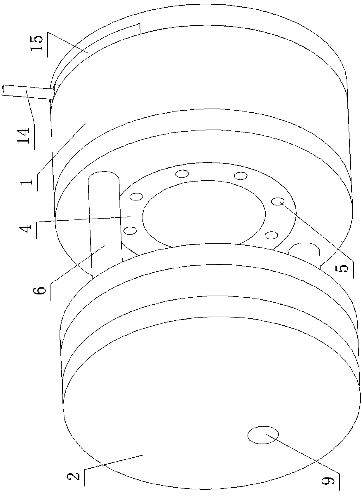
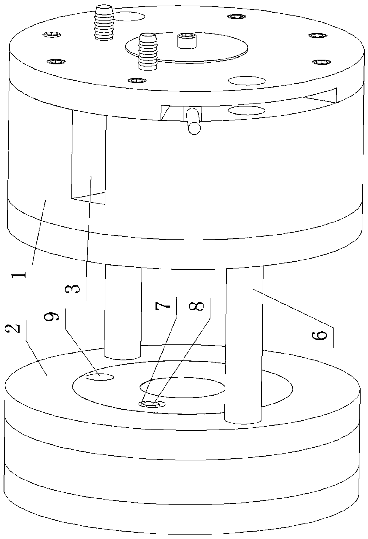
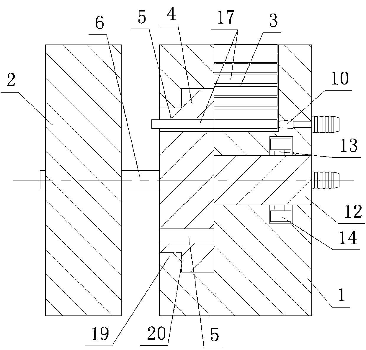
[0018] Such as figure 1 , figure 2 , image 3 , Figure 4 , Figure 5 , Image 6 As shown, the stamping die of the present invention includes a cylindrical formwork 1 and a punch 2 . The cylindrical formwork 1 is provided with a radial blanking channel 3 whose opening is located on the outer peripheral surface. The front end surface of the cylindrical formwork 1, that is, the end surface close to the punch 2, is provided with a first cylindrical recess, and a turntable 4 is rotatably fitted in the first cylindrical recess. Specifically, the opening of the first cylindrical pit is provided with a limit ring 19, and the circumferential surface of the turntable 4 is provided with a limit step 20 against the limit ring 19, and the limit step 20 prevents the turntable 4 from breaking away from the first Cylindrical pit. The front end face o...


PUM


Abstract

The invention discloses a stamping die which comprises a cylindrical die shell (1) and a punch (2). The cylindrical die shell (1) is provided with a radial material falling channel, a rotary table (4) is matched in the cylindrical die shell (1) in a rotatable mode, the rotary table (4) is provided with a plurality of circular through holes (5), the punch (2) is arranged on a guide column (6) in a sliding fit mode, the punch (2) is provided with a second cylindrical pit (7), a hexagonal prism protrusion (8) is arranged at the pit bottom of the second cylindrical pit (7), and a material discharging hole (9) is further formed in the punch (2). The radial material falling channel is communicated with one circular through hole (5), and the second cylindrical pit (7) right faces one circular through hole (5). The material discharging hole (9) right faces another circular through hole (5), and the cylindrical die shell (1) is provided with a second sprayer (11) for spraying stamped and formed screws (18) into the material discharging hole (9). The stamping die is high in stamping process speed and efficiency, safe, and convenient to use.

Description

technical field [0001] The invention relates to the technical field of molds, in particular to a stamping mold for stamping screws. Background technique [0002] The stamping die of the traditional stamping screw includes a lower die and an upper die. The upper end of the lower die is provided with a blind hole that matches the shape of the screw, that is, the lower die cavity. The lower end of the upper die is provided with cylindrical pits. The top is provided with hexagonal prism protrusions, and the cavity between the cylindrical recess and the hexagonal prism protrusions constitutes an upper die cavity that matches the shape of the head of the hexagon socket head screw, and the centerlines of the upper and lower die cavities coincide. Fix the lower mold, and put a round rod into the lower mold cavity. The length of the round rod is greater than the height of the lower mold cavity, and the upper mold and the punch are fixed. Drive the punch to make the two molds close to...

Claims


Application Information

Patent Timeline
Patent Type & Authority Applications(China)
IPC IPC(8): B21D37/10B21D45/00
Inventor 陆昱森
Owner 广州市烁烨金属制品有限公司
Why Eureka
Try Eureka