Robot driving structure

A driving structure and robot technology, applied in the field of machinery, can solve problems such as difficulty in making great breakthroughs in the working radius and load capacity of the robot driving structure, limiting the load capacity and working radius of the robot driving structure, and affecting the positioning accuracy of the robot driving structure. The effect of low structural strength, reduced self-weight, and improved accuracy

Active Publication Date: 2013-12-04
范红兵
View PDF7 Cites 16 Cited by
  • Summary
  • Abstract
  • Description
  • Claims
  • Application Information

AI Technical Summary

Problems solved by technology

At the same time, this kind of structural setting will make the small error of the power device in the center be amplified at the end of the swing arm, reducing the accuracy of the operation
That is to say, the structure and driving form of the existing articulated robot drive structure not only limit the load capacity and working radius of the robot drive structure, but also affect the positioning accuracy of the robot drive structure.
[0009] Even if the power unit of the first joint arm 2 of some ar

Method used


Image

  • Robot driving structure
  • Robot driving structure
  • Robot driving structure

Examples


Embodiment Construction

[0019] The core of the present invention is to provide a robot driving structure, which can significantly improve its working radius and working precision with less energy consumption.

[0020] In order to enable those skilled in the art to better understand the solutions of the present invention, the present invention will be further described in detail below in conjunction with the accompanying drawings and specific embodiments.

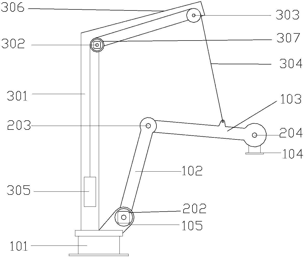
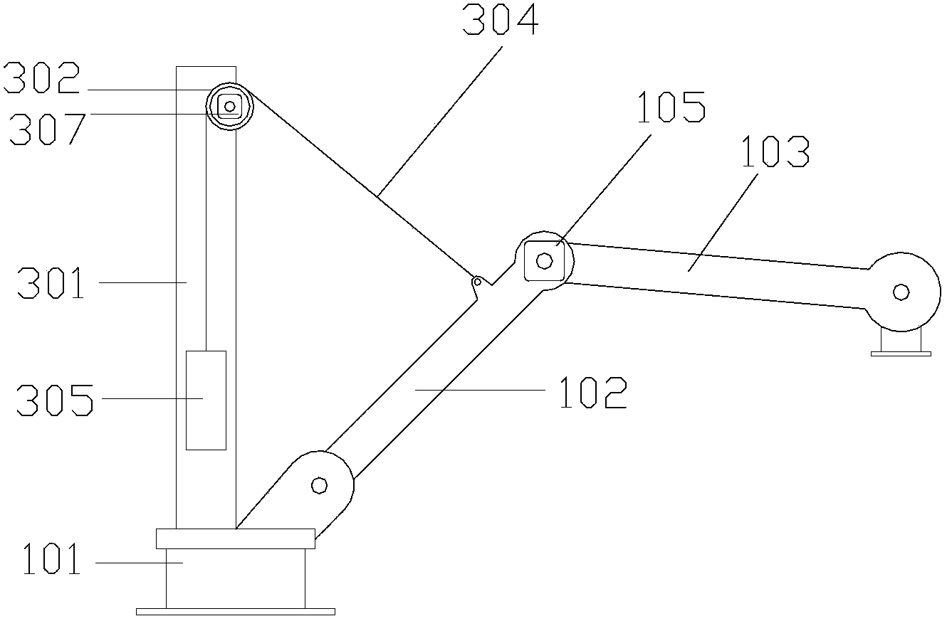
[0021] Please refer to figure 2 , figure 2 It is a structural schematic diagram of a specific embodiment of the robot driving structure provided by the present invention.

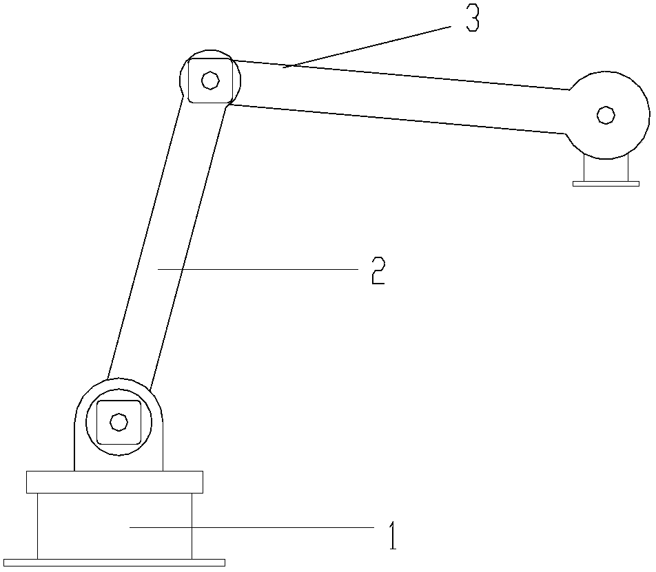
[0022] The existing robot drive structure generally includes a base 101 and a mechanical arm pivotally mounted on the base 101 .

[0023] Wherein, the mechanical arm includes a first joint arm 102 , a second joint arm 103 and a third joint arm 104 which are sequentially connected to each other. Usually, the self-rotating axis of the base is called the first axis (not shown ...


PUM


Abstract

A robot driving structure has a base (101), a first arm (102) hinged to the base (101), a second arm (103) hinged to the first arm (102), at least two servo power units (105, 307), and a driving wheel (302) and a flexible rope (304) which are arranged on the base (101). The driving wheel (302) is connected to the base (101) by a supporting arm; one servo power unit (105) is provided between the base (101) and the first arm (102), and the driving wheel (302) is connected to another servo power unit (307). The flexible rope (304) is engaged with the driving wheel (302), and one end of the flexible rope (304) is connected to the second arm (103).Driven by the driving wheel (302), the flexible rope (304) pull the second arm (103) to swing, and the two servo power units (105, 307) drive the first arm (102) and the second arm (103) together to realize a coordination movement. The joint of the flexible rope (304) and the second arm (103) is located on the far end of the second arm (103), thus the driving force can be applied more directly, and the working accuracy and the load capacity of the driving structure can be improved.

Description

technical field [0001] The invention relates to a driving structure in the technical field of machinery, in particular to a driving structure of an articulated robot. Background technique [0002] There are many types of robot driving structures in the prior art, and the articulated robot driving structure is widely used because of its flexibility, and has become the main form of robot driving mechanical structures. The driving structure of the articulated robot has the advantages of small motion inertia, small resistance, and many attitude changes, and is widely used in palletizing, handling, welding, and spraying. [0003] Please refer to figure 1 , figure 1 It is a structural schematic diagram of a setting method of a robot in the prior art. [0004] The driving structure of the articulated robot mainly includes: a rotatable base 1, a first joint arm 2 with one end hinged to the base, and a second joint arm 3 with one end hinged to the first joint arm, and the other en...

Claims


Application Information

Patent Timeline
IPC IPC(8): B25J9/00B25J19/00
CPCB25J19/002B25J9/047B25J9/104
Inventor 范红兵
Owner 范红兵
Why Eureka
Try Eureka