
Lighting system and construction machinery

A technology for lighting systems and construction machinery, applied to earth movers/shovels, buildings, optical signals, etc., can solve problems such as hidden dangers of safe operation of excavators, decreased operating efficiency, and inconvenience in night work, so as to improve operational safety , improve work efficiency, and eliminate lighting blind spots

Inactive Publication Date: 2015-10-28
SANY HEAVY MACHINERY
View PDF4 Cites 2 Cited by
  • Summary
  • Abstract
  • Description
  • Claims
  • Application Information

AI Technical Summary

Problems solved by technology

However, the axis of the headlight is parallel and fixed to the axis of the upper body, and the direction of beam irradiation of the headlight is the same as that of the upper body. In the front area, there are prone to lighting blind spots, so that the operator cannot accurately judge the situation in the adjacent area ahead, and cannot obtain sufficient information on the working conditions ahead, leaving serious hidden dangers for the safe operation of the excavator and bringing great harm to night work. inconvenient
[0003] Especially during the slewing operation, it is impossible to observe the working conditions of the area to be turned in advance, causing visual obstacles, causing a decrease in operating efficiency, and easily causing accidents such as collisions

Method used


Image

  • Lighting system and construction machinery
  • Lighting system and construction machinery

Examples


no. 1 example

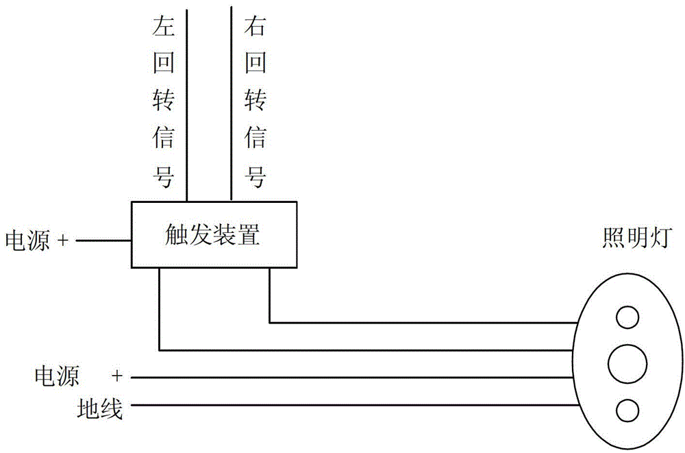
[0027] refer to figure 1 , shows the lighting system of this embodiment, and the lighting system includes: a power supply device, a signal acquisition device for collecting rotation signals, a trigger device, a main lighting lamp and an auxiliary lighting lamp for expanding the lighting area. Wherein, the main lighting lamp and the auxiliary lighting lamp are connected to the power supply device, and the trigger device is arranged on the connection line between the auxiliary lighting lamp and the power supply device. The trigger device is connected with the signal acquisition device, and is used to control the opening and closing of the auxiliary lighting lamp according to the rotation signal.

[0028] In this example, if figure 1 As shown, the lighting includes main lighting and auxiliary lighting. Among them, the main lighting is used to illuminate the area in the same direction as the axle, and the auxiliary lighting can be used to activate the auxiliary lighting function...

no. 2 example

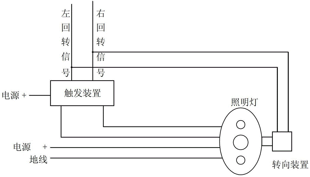
[0036] refer to figure 2 , shows the lighting system of this embodiment, and the lighting system includes: a power supply device, a signal acquisition device for collecting a slewing signal, a trigger device, a main lighting lamp, an auxiliary lighting lamp for expanding the lighting area, and a A turn signal that changes the direction of the lighting. Wherein, the main lighting lamp and the auxiliary lighting lamp are connected to the power supply device, and the trigger device is arranged on the connection line between the auxiliary lighting lamp and the power supply device. The steering unit is connected to the main and auxiliary lights. The trigger device is connected with the signal acquisition device, and is used to control the opening and closing of the auxiliary lighting lamp according to the rotation signal.

[0037] In an optional embodiment, the steering device includes: a first steering device for controlling the lighting direction to turn left, and a second ste...


PUM


Abstract

The invention discloses an illuminating system and engineering machinery. The illuminating system comprises a power source device, a signal collecting device for collecting turn signals, a trigger device, a primary floodlight and auxiliary floodlights used for enlarging illuminating areas. The primary floodlight and the auxiliary floodlights are connected with the power source device, the trigger device is arranged on a connecting wire between the auxiliary floodlights and the power source device, the trigger device is connected with the signal collecting device and used for controlling the auxiliary floodlights to be turned on and turned off according to the turn signals, therefore, illumination blind zones existing during turn are eliminated, the visual field is enlarged, an operator can observe the working conditions of a zone in advance towards which a machine is turned, and operation efficiency is improved.

Description

technical field [0001] The invention relates to the field of construction machinery, in particular to an illumination system and construction machinery. Background technique [0002] At present, excavators, as the most commonly used construction machinery, have a high probability of being used at night. However, the axis of the headlight is parallel and fixed to the axis of the upper body, and the direction of beam irradiation of the headlight is the same as that of the upper body. In the front area, there are prone to lighting blind spots, so that the operator cannot accurately judge the situation in the adjacent area ahead, and cannot obtain sufficient information on the working conditions ahead, leaving serious hidden dangers for the safe operation of the excavator and bringing great harm to night work. inconvenient. [0003] Especially during the slewing operation, it is impossible to observe the working conditions of the area to be turned in advance, causing visual ob...

Claims


Application Information

Patent Timeline
Patent Type & Authority Patents(China)
IPC IPC(8): B60Q1/24E02F9/00E02F3/00
Inventor 徐熙庆刘天勋
Owner SANY HEAVY MACHINERY
Learn More