Micromechanical component and method for manufacturing a micromechanical component

A micro-mechanical and micro-mechanical structure technology, which is applied in the direction of electrical components, manufacturing micro-structural devices, micro-structural technology, etc., can solve the problems of increased manufacturing costs such as scrap rate

Inactive Publication Date: 2013-12-04
ROBERT BOSCH GMBH
View PDF12 Cites 15 Cited by
  • Summary
  • Abstract
  • Description
  • Claims
  • Application Information

AI Technical Summary

Problems solved by technology

If liquid phases or eutectics then enter the structural region of the carrier substrate or cap substrate, this can lead, for example, to localized transportable masses of sensor structures that are originally movable, such as acceleration sensors or rotational speed sensors. fixed, such a micromechanical component can no longer be used later, resulting in increased scrap rates and manufacturing costs

Method used


Image

  • Micromechanical component and method for manufacturing a micromechanical component
  • Micromechanical component and method for manufacturing a micromechanical component
  • Micromechanical component and method for manufacturing a micromechanical component

Examples


Embodiment Construction

[0024] In different figures, the same reference numerals designate the same elements, and are therefore generally named or mentioned only once in each case.

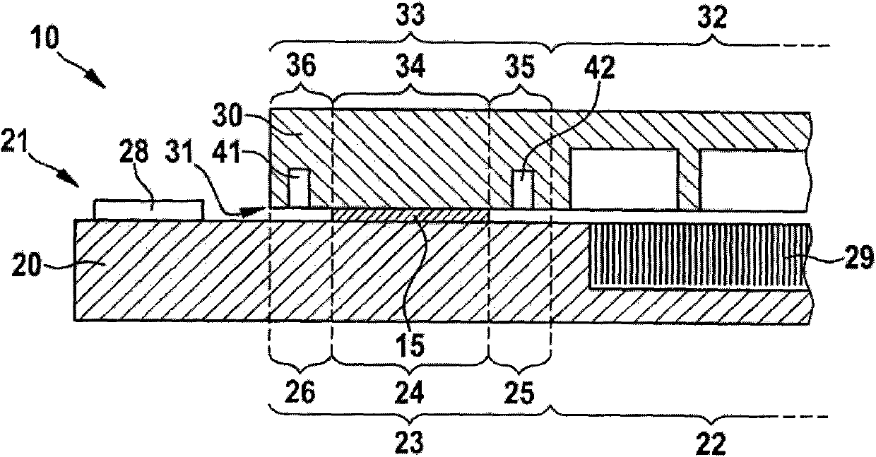
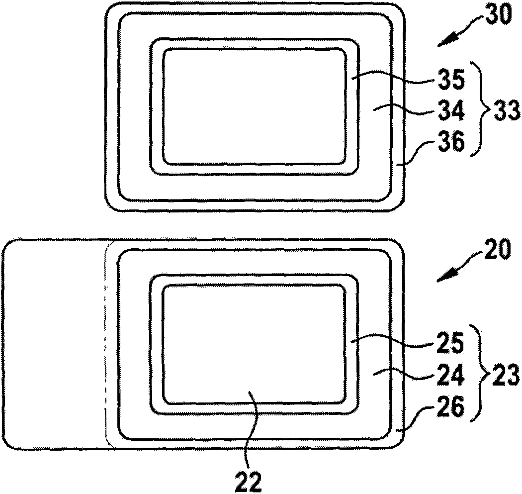
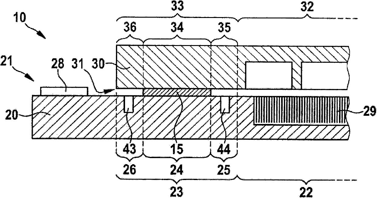
[0025] figure 1, 3, 4, 5, 6 and 7 respectively show a part of a micromechanical component 10 according to the invention in a schematic cross-sectional view, wherein the micromechanical component 10 comprises a carrier substrate 20 and a cap substrate 30 . The carrier substrate 20 has a first connection side 21 and the cap substrate 30 has a second connection side 31, wherein the carrier substrate and the cap substrate 20, 30 face each other with their respective connection sides 21, 31 Connection wherein, according to the invention, eutectic bonding (or soldering) is provided in the edge regions of carrier substrate and cap substrate 20 , 30 . The carrier substrate 20 has a first structure region 22 and a first edge region 23 , wherein, according to the invention, the first edge region 23 has at least a first connectio...


PUM


Abstract

A micromechanical component, in particular a micromechanical sensor having a carrier substrate and having a cap substrate, and a manufacturing method are provided. The carrier substrate and the cap substrate are joined together with the aid of a eutectic bond connection or by a metallic solder connection or a glass solder connection (e.g., glass frit), in an edge area of the carrier substrate and the cap substrate. The connection of the carrier substrate and the cap substrate is established with the aid of connecting areas, and a stop trench or a stop protrusion or both a stop trench and a stop protrusion are situated within the edge areas in the bordering areas.

Description

Background technique [0001] The invention relates to a micromechanical component according to the preamble of claim 1 . [0002] Such micromechanical components are already widely known. For example, from document DE 10 2007 044 806 A1 a micromechanical component has been disclosed comprising a first wafer and a second wafer, wherein the first wafer has at least one structural element and the second wafer has at least one corresponding structural element, wherein the first A wafer and / or a second wafer has a functional area which is surrounded by a sealing area. [0003] In eutectic bonding, two materials are usually brought into contact which have a lowest melting point in their phase diagram, ie the so-called eutectic point. At corresponding temperatures and corresponding mixing conditions, the two materials melt and form a eutectic. In this case, the melting of the materials takes place below the melting temperature of the respective bonding material. [0004] Since the...

Claims


Application Information

Patent Timeline
Patent Type & Authority Applications(China)
IPC IPC(8): B81B7/00B81C1/00
CPCB81C1/00269B81B7/007B81C2203/019B81C1/00301B81C2203/035B81C2203/0109
Inventor J·贡斯卡J·弗莱H·韦伯T·沙里T·迈尔
Owner ROBERT BOSCH GMBH
Why Eureka
Try Eureka