A centrifugal degassing pump

A delivery pump and centrifugal technology, applied in the field of centrifugal degassing delivery pumps, can solve the problems that the degassing effect cannot reach the best state, and achieve the convenience of automatic large-scale production, fast degassing and delivery speed, and low operation and maintenance costs low effect

Active Publication Date: 2016-03-09
ZHEJIANG UNIV
View PDF9 Cites 0 Cited by
  • Summary
  • Abstract
  • Description
  • Claims
  • Application Information

AI Technical Summary

Problems solved by technology

However, this patent does not do relevant treatment before the liquid enters the runner device, and the degassing effect cannot reach the best state. This patent can make further improvements in degassing to make the degassing effect better

Method used


Image

  • A centrifugal degassing pump
  • A centrifugal degassing pump
  • A centrifugal degassing pump

Examples


Embodiment 1

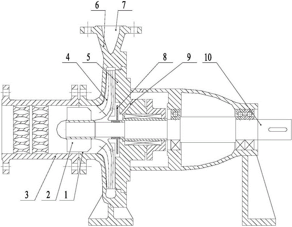
[0047] Such as figure 1 As shown, a centrifugal degassing delivery pump includes a housing 6 with a pump shaft 10 inside. The housing 6 is provided with an air pumping channel 9 for an external vacuum pumping device. The housing 6 is provided with an inlet 1 and a The outlet 7 and the inlet 1 of the housing are connected with a throttling device 3 for gas-liquid pre-separation. The pump shaft 10 is provided with a pre-separation impeller 2, a main impeller 4 and a first sealing impeller 8 in sequence along the axial direction. The separation impeller 2 is installed on the end of the pump shaft 10 close to the inlet, and the first sealing impeller 8 is arranged between the main impeller 4 and the suction passage 9 .

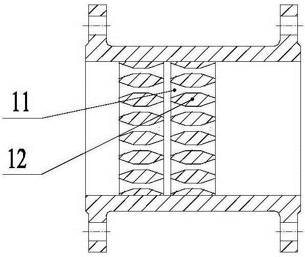
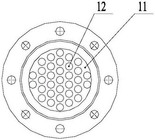
[0048] Such as figure 2 , As shown in 3, the throttling device 3 is an air analysis pipe, and the air analysis pipe is provided with a baffle 11 with a throttle hole 12 on the baffle. The function of the baffle is to increase the flow rate of the liquid, reduce...

Embodiment 2

[0056] Such as Figure 14 As shown, another form of centrifugal degassing delivery pump, this embodiment adds an exhaust channel 23 on the basis of embodiment 1, and the exhaust channel is arranged between the inlet 1 of the casing and the front separation impeller 2, the pump shaft 10 extends into the exhaust passage 23, and a second sealing impeller 24 fixed to the pump shaft and used to return the liquid is arranged in the exhaust passage 23. One end of the exhaust passage is connected with a vacuum pumping device, and an exhaust chamber 28 for accommodating the second sealed impeller 24 is provided in the exhaust passage 23. The inlet 27 connected to the inner cavity, and the outlet facing away from the pre-separation impeller 2; the pump shaft 10 extends from the inlet 27 to the exhaust chamber 28, and the exhaust chamber 28 is provided with a connection with the casing at a position far away from the axis of the pump shaft. The backflow channel 26 connected with the inn...


PUM


Abstract

The invention discloses a centrifugal degassing delivery pump which comprises a shell, wherein a pump shaft is arranged in the shell; the shell is provided with a bleed-off passage for being externally connected with a vacuum gas extracting device; the shell is provided with an inlet and a discharge port; the inlet of the shell is connected with a throttling device for gas-liquid pre-separation; the pump shaft is sequentially provided with a front-mounted separation impeller, a main impeller and a first sealing impeller; the pre-impeller separation impeller is arranged at one end of the pump shaft, which is close to the inlet; the first sealing impeller is arranged between the main impeller and the bleed-off passage. Gas in liquid is separated out by the throttling device through utilizing the characteristic that solubility of the gas in the liquid is reduced with reduction of the pressure; then gas-liquid separation is implemented by utilizing different acting effects of a centrifugal force of the impellers on the gas and the liquid. The centrifugal degassing delivery pump has a good degassing effect and high degassing and delivery speed, is convenient for automatic scale production and is lower in operation and maintenance cost.

Description

technical field [0001] The invention relates to a liquid degassing device, in particular to a centrifugal degassing delivery pump, which is used for removing air bubbles and gas dissolved in the liquid while transporting the liquid. Background technique [0002] In the food industry, it is often necessary to remove the dissolved gas in the liquid and separate the gas in it. Such as the degassing operation of juice and milk to prevent the oxidation of juice and prolong the storage period. Vacuum degassing tanks are commonly used in the food industry to degas the feed liquid. Vacuum degassing tanks are also known as vacuum degassers and vacuum degassers. Its function is to remove air (oxygen) in the feed liquid, inhibit browning, Oxidation of pigments, vitamins, aroma components and other substances to prevent quality degradation; remove suspended particulate gas attached to the material liquid, inhibit the floating of particles, and maintain a good appearance; prevent bubble...

Claims


Application Information

Patent Timeline
Patent Type & Authority Patents(China)
IPC IPC(8): B01D19/00
Inventor 武鹏吴大转
Owner ZHEJIANG UNIV
Why Eureka
Try Eureka