Concentrated-winding motor, generator and motor

A technology of concentrated winding and generator, applied in the direction of magnetic circuit rotating parts, magnetic circuit shape/style/structure, magnetic circuit static parts, etc. The effect of good sinusoidal magnetic field and constant torque

Active Publication Date: 2013-12-04
深圳市大富动力装备有限公司
View PDF8 Cites 2 Cited by
  • Summary
  • Abstract
  • Description
  • Claims
  • Application Information

AI Technical Summary

Problems solved by technology

Therefore, the most effective measure for the traditional distributed winding permanent magnet motor to suppress the positioning torque, the concentrated w

Method used


Image

  • Concentrated-winding motor, generator and motor
  • Concentrated-winding motor, generator and motor
  • Concentrated-winding motor, generator and motor

Examples


Embodiment Construction

[0025] The following will clearly and completely describe the technical solutions in the embodiments of the present invention with reference to the accompanying drawings in the embodiments of the present invention. Obviously, the described embodiments are only some, not all, embodiments of the present invention. Based on the embodiments of the present invention, all other embodiments obtained by persons of ordinary skill in the art without creative efforts fall within the protection scope of the present invention.

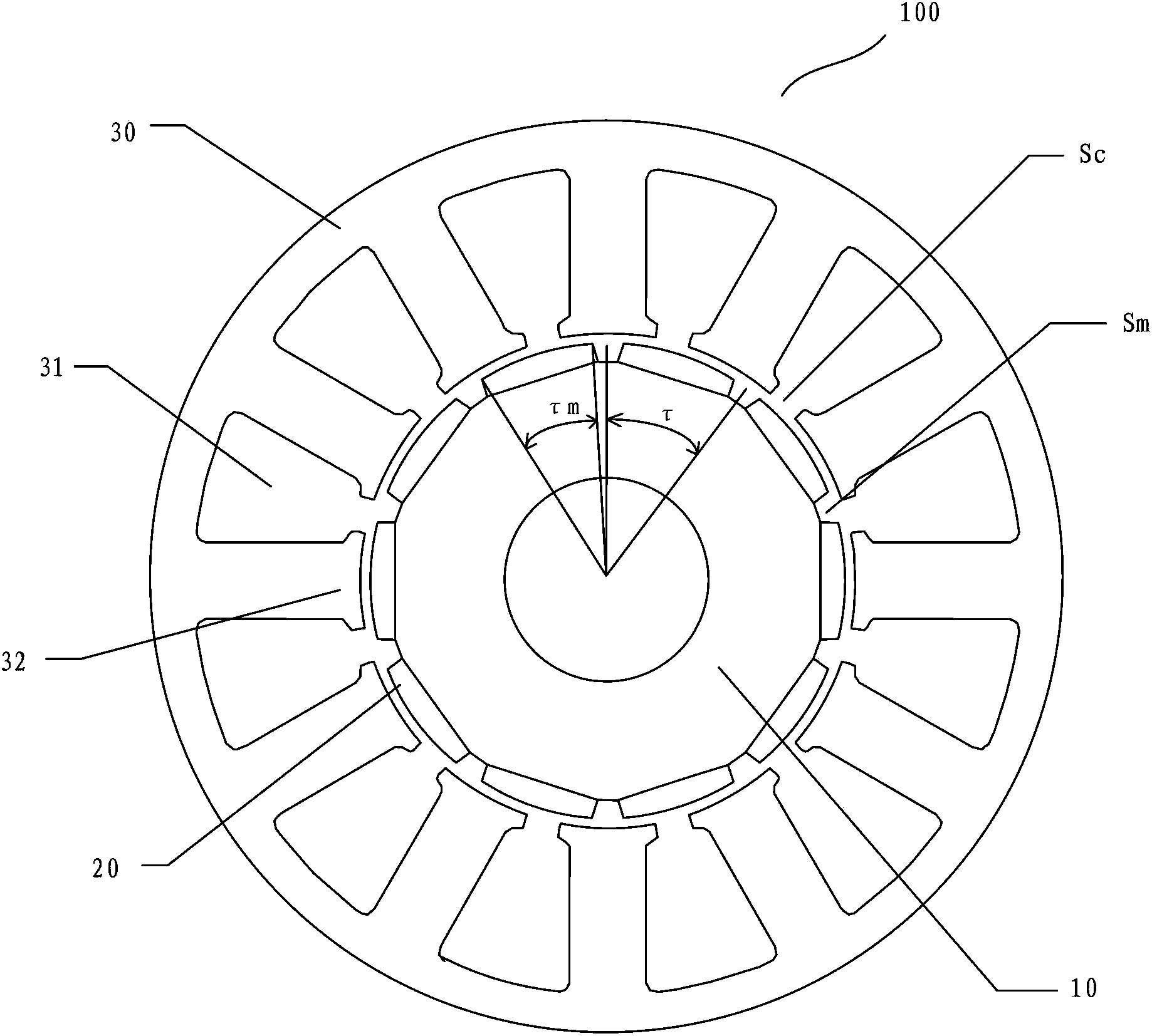
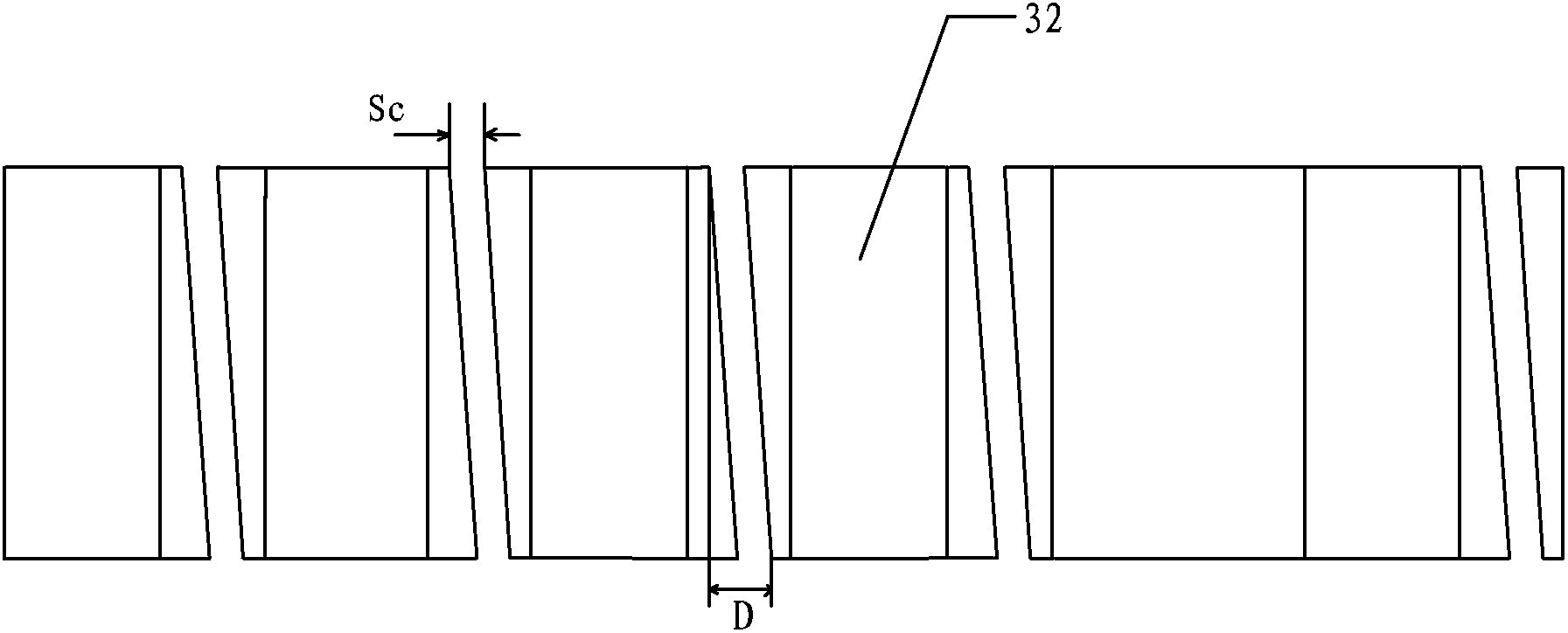
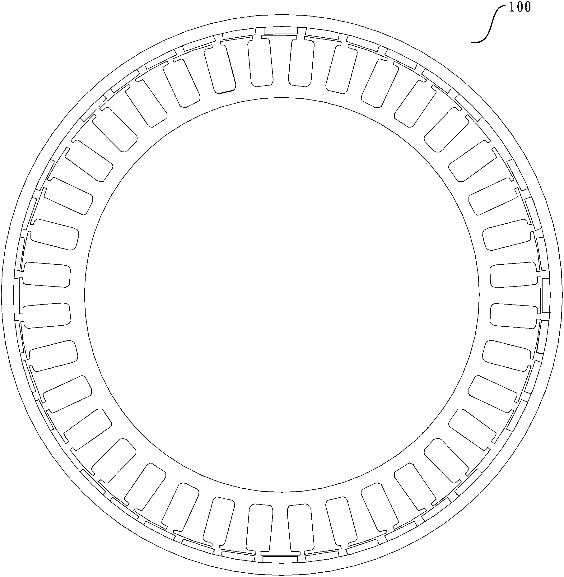
[0026] Such as figure 1 As shown, a concentrated winding motor 100 of the present invention, the rotor yoke 10 is pasted with 2P pieces of magnetic steel 20 with N and S polarities distributed alternately with a spacing of Sm, and the stator core 30 is provided with Z slots 31 and Z Stator teeth 32. According to traditional theoretical analysis and experiments, the period of the positioning torque of the permanent magnet motor with the number of poles and slots is...


PUM


Abstract

The invention relates to concentrated-winding permangent magnet motors, in particular to a concentrated-winding motor, a generator and a motor. Magnets adhere to a rotor yoke of the concentrated-winding motor, wherein the distance between every two steel magnets is Sm, the N poles of the steel magnets and the S poles of the steel magnets are distributed alternately, and the number of the steel magnets is 2P. A stator core is provided with Z grooves and Z stator teeth, the width Sc of a notch between every two adjacent stator teeth of the concentrated-winding motor and the distance Sm between every two adjacent steel magnets meet the constraint relationship Sm/Sc=(0.83-1.3), and the ratio of the width of each steel magnet to the pole pitch tau of each steel magnet meets the constraint relationship taum/tau >=(0.75-0.9), wherein the pole pitch tau is equal to 360 degrees/2P, and P is the number of pole pairs of the motor. According to the concentrated-winding motor, the interval-adhering type steel magnets are adopted, materials are saved, an air-gap magnetic field is good in sine, the location torque of the motor is small, and the notches of the motor can fully meet the requirements of direct full-automatic winding.

Description

technical field [0001] The invention relates to a permanent magnet motor with concentrated winding, in particular to a concentrated winding motor, generator and motor. Background technique [0002] The rotors of permanent magnet motors generally use rare earth permanent magnets, such as NdFeB permanent magnets. Rare earth permanent magnet materials are becoming scarcer and more expensive, so it is necessary to reduce the amount of permanent magnets and improve the utilization rate of permanent magnets. [0003] Permanent magnet motors with concentrated windings can significantly improve the power and energy indicators of permanent magnet motors, such as: winding utilization, efficiency, power volume ratio, torque volume ratio, etc., and improve the motor manufacturing process. [0004] However, the excessively large cogging torque is still a problem for concentrated winding permanent magnet motors. The optimal number of magnetic poles and cogging slots can suppress the cogg...

Claims


Application Information

Patent Timeline
IPC IPC(8): H02K1/16H02K1/27
Inventor 漆亚梅
Owner 深圳市大富动力装备有限公司
Why Eureka
Try Eureka