Braking apparatus for three-phase brushless motor

A technology of brushless motors and braking devices, which is applied to the deceleration device of AC motors, stop devices, electric motor/converter plugs, etc., can solve the problems of damaging the user's sense of use and increasing the reaction force, and prevent Effects of adverse effects, reduction of withstand voltage, and cost reduction

Active Publication Date: 2013-12-04
MAKITA CORP
View PDF7 Cites 13 Cited by
  • Summary
  • Abstract
  • Description
  • Claims
  • Application Information

AI Technical Summary

Problems solved by technology

[0008] In addition, for example, in a cordless circular saw that uses a 3-phase brushless motor to rotate the circular saw at high speed, if the brake is applied by the conventional short-circuit brake, the braking force is too strong, so the reaction force becomes larger, impairing the use of the saw. user experience

Method used


Image

  • Braking apparatus for three-phase brushless motor
  • Braking apparatus for three-phase brushless motor
  • Braking apparatus for three-phase brushless motor

Examples


Embodiment Construction

[0054] Embodiments of the present invention will be described below based on the drawings.

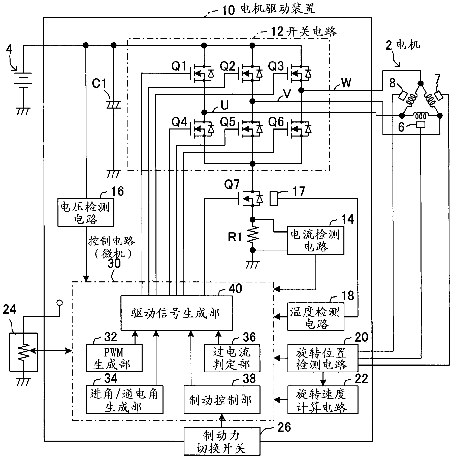
[0055] In this embodiment, it is a motor used when driving a three-phase brushless motor (hereinafter simply referred to as a motor) 2 as a power source in electric equipment such as the above-mentioned cordless lawn mower or cordless saw. The present invention is applied to the driving device 10 .

[0056] like figure 1 As shown, the motor drive device 10 of this embodiment includes a power supply line connected to the positive side of the battery 4 as a DC power supply, and a ground line connected to the negative side of the battery 4 .

[0057] Furthermore, a switch circuit 12 for controlling the current flowing in each phase U, V, and W of the motor 2 is provided between the power supply line on the positive side and the ground line on the negative side.

[0058] The switching circuit 12 consists of three switching elements Q1, Q2, Q3 (specifically, the U-phase high-voltage end s...


PUM


Abstract

A braking apparatus (6, 7, 8, 12, 20, 30) for a three-phase brushless motor (2) according to one aspect of the present invention is provided in a motor-driven appliance (100), and includes a switching circuit (12) having six switching elements (Q1, Q2, Q3, Q4, Q5, Q6) and a brake control device (30). The brake control device (30) executes two-phase short-circuit control in braking control in which a braking force is generated in the motor (2). In the two-phase short-circuit control, an on/off state of each of the switching elements (Q1, Q2, Q3, Q4, Q5, Q6) is set in such a manner that two out of three conduction paths constituting one of a positive electrode side conduction path that connects three terminals (U, V, W) of the motor (2) and a positive electrode side of a direct current power source (4) and a negative electrode side conduction path that connects the three terminals (U, V, W) and a negative electrode side of the power source (4) are in a conducting state and other of the three conduction paths is in a non-conducting state.

Description

technical field [0001] The present invention relates to a braking device for a three-phase brushless motor that generates a braking force by short-circuiting terminals of the three-phase brushless motor. Background technique [0002] Conventionally, in electrical equipment using a 3-phase brushless motor as a power source, when reducing or stopping the rotation of the 3-phase brushless motor, short-circuiting between terminals of the 3-phase brushless motor is used to generate a braking force. So-called short-circuit braking (for example, refer to Patent Document 1). [0003] In this short-circuit braking, for example, by turning on three switching elements (so-called low-voltage side switches) provided on the conduction path between each terminal of the 3-phase brushless motor and the negative pole of the DC power supply, the Three switching elements (so-called high-voltage side switches) provided on the energization path between each terminal of the 3-phase brushless moto...

Claims


Application Information

Patent Timeline
Patent Type & Authority Applications(China)
IPC IPC(8): H02P6/24
CPCH02P3/06H02P6/24H02P3/22A01D34/69
Inventor 市川佳孝
Owner MAKITA CORP
Why Eureka
Try Eureka