Unlock instant, AI-driven research and patent intelligence for your innovation.
Adhesive sticker plane die cutting method
What is Al technical title?
Al technical title is built by PatSnap Al team. It summarizes the technical point description of the patent document.
A flat die-cutting and die-cutting technology, applied in metal processing and other directions, can solve problems such as the inability to complete die-cutting normally, and achieve the effect of broadening the scope of use, improving enterprise efficiency and reducing processing costs.
Active Publication Date: 2015-04-08
SHENYANG LIGONG UNIV
View PDF5 Cites 0 Cited by
Summary
Abstract
Description
Claims
Application Information
AI Technical Summary
This helps you quickly interpret patents by identifying the three key elements:
Problems solved by technology
Method used
Benefits of technology
Problems solved by technology
[0013] When the present invention borrows a knife line for the knife edge, due to the thickness of the knife strip, there is a distance of the knife strip thickness at the position where the knife edge is tangent on the borrowed knife line, and For the problem that the die-cutting cannot be completed normally, a self-adhesive plane die-cutting method is provided, which is divided into two sub-step positions for die-cutting, which broadens the scope of use of the plane die-cutting machine
Method used
Image
Click on the blue label to locate the original text in one second.
Reading with bidirectional positioning of images and text.
Examples
Embodiment 1
[0061] The first step is to draw step-by-step blade graphics.
[0062] Based on the shapes of the two tangent stickers, draw a knife edge shape that is the same shape as the edge of the two tangent stickers. CAD software can be used to draw. The two tangent self-adhesive labels are respectively a first self-adhesive label and a second self-adhesive label.
[0063] This is the case where the lending line EF in the tool is the same as the paper pulling direction.
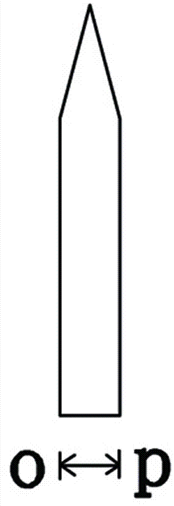
[0064] The blade pattern on the borrow line and its left part is called the first blade graph 1, and the blade graph on the right part (excluding the borrow line) of the borrow line is called the second blade graph 2, which is called a line, as Figure 6 shown. Both the length of the first blade pattern 1 and the second blade pattern 2 are a, and the widths are both b. At this time, the paper pulling step length is L=b+c. The distance between two adjacent rows of blade patterns is c.
[0065] Bundle Figure 6 a...
Embodiment 2
[0081] The first step is to draw step-by-step blade graphics.
[0082] According to the shapes of the two tangent stickers, draw a knife-edge figure with the same shape as the edges of the two tangent stickers, which is called a row.
[0083] This is the case where the lending line EF in the tool is perpendicular to the paper-drawing direction.
[0084] The blade pattern of the loan line and its upper part is called the first blade pattern 1, and the blade pattern of the part below the loan line (excluding the loan line) is called the second blade pattern 2, as Figure 13 , the length of the first blade pattern 1 and the second blade pattern 2 is a, the width is b, and the distance between two adjacent rows of blade patterns is c. At this time, the paper pulling step length L=2b+c.
[0085] Bundle Figure 13 according to Figure 13 The paper-drawing step length L and then copy a group such as Figure 14 .
[0086] Keep the first blade pattern 1 in the first row, and dele...
PUM
Abstract
A self-adhesive planar die-cutting method comprises the following steps: drawing step-by-step blade graphics; drawing the blade graphics according to the shape of the tangent self-adhesivelabel; the knife-edge graphics on the borrowed line and one side of the borrowed line are called the first knife-edge graphics The other side of the borrowed line is partly planed out of the borrowed line, which is called the second knifed edge figure; the step-by-step knifed edge figure includes at least one first knifed edge figure and at least one second knifed edge figure. The two blades die-cut two self-adhesive labels respectively. The self-adhesive material is first moved to the first edge for die-cutting, and then moved to the second edge for die-cutting; wood boards are processed, and machete strips are made into step-by-step knives. Stick the step cutter to the upper blade of the flat die cuttingmachine for die cutting. Two-blade graphics can be arranged left and right or up and down. The invention expands the application range of the plane die-cutting machine by making the plane die-cutting tool which cannot be die-cut in the blade tangential mode into a step-by-step tool.
Description
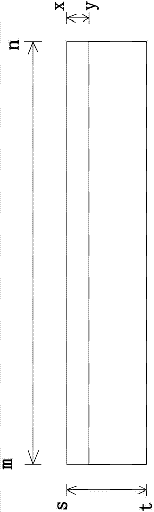
technical field [0001] The invention belongs to the field of self-adhesive plane die-cutting methods, in particular to a self-adhesive plane die-cutting method. Background technique [0002] Self-adhesive die-cutting is to process continuous roll-shaped self-adhesive materials into labels through a die-cutting machine, which is divided into two types: flat die-cutting and hob die-cutting. Flat die-cutting machines have a very high market share due to the simple production of die-cutting tools and low price (the general production cost is about tens of yuan), and the market share of hob die-cutting tools is very high due to the high production cost (generally around several thousand yuan). The rate is very low. [0003] The planar die-cutting tool is composed of two parts: a board and a blade. The board is a professional board with a thickness of 7mm. The shape of the blade is as follows: figure 1 (front view of blade). The length mn of the unbent blade is 910mm, the overa...
Claims
Application Information
Patent Timeline
Application Date:The date an application was filed.
Publication Date:The date a patent or application was officially published.
First Publication Date:The earliest publication date of a patent with the same application number.
Issue Date:Publication date of the patent grant document.
PCT Entry Date:The Entry date of PCT National Phase.
Estimated Expiry Date:The statutory expiry date of a patent right according to the Patent Law, and it is the longest term of protection that the patent right can achieve without the termination of the patent right due to other reasons(Term extension factor has been taken into account ).
Invalid Date:Actual expiry date is based on effective date or publication date of legal transaction data of invalid patent.

