Optical fiber core butt joint device

An optical fiber core and equipment technology, applied in the field of optical fiber core docking equipment, can solve the problems of huge workload, time-consuming, and tedious manual switching operations.

Active Publication Date: 2013-12-11
STATE GRID CORP OF CHINA +1
View PDF3 Cites 21 Cited by
  • Summary
  • Abstract
  • Description
  • Claims
  • Application Information

AI Technical Summary

Problems solved by technology

However, due to geographical dispersion, cumbersome manual switching operations and many other factors, such manual operations in daily life are huge and time-consuming. Therefore, how to realize the automatic docking and exc

Method used


Image

  • Optical fiber core butt joint device
  • Optical fiber core butt joint device
  • Optical fiber core butt joint device

Examples


Embodiment 1

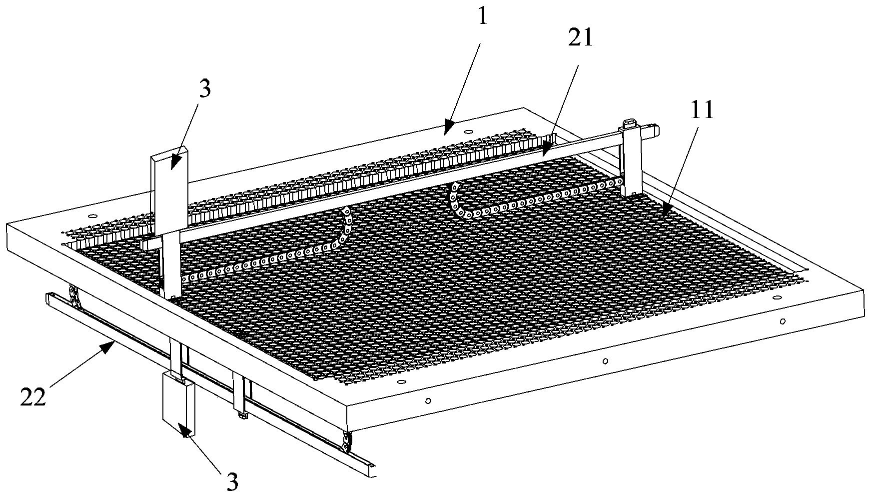
[0049] Such as figure 1 As shown, the embodiment of the present invention provides an optical fiber core butt joint device, including

[0050] A docking plate 1 having a plurality of docking devices, wherein the docking devices include a docking hole 11 at the center thereof;

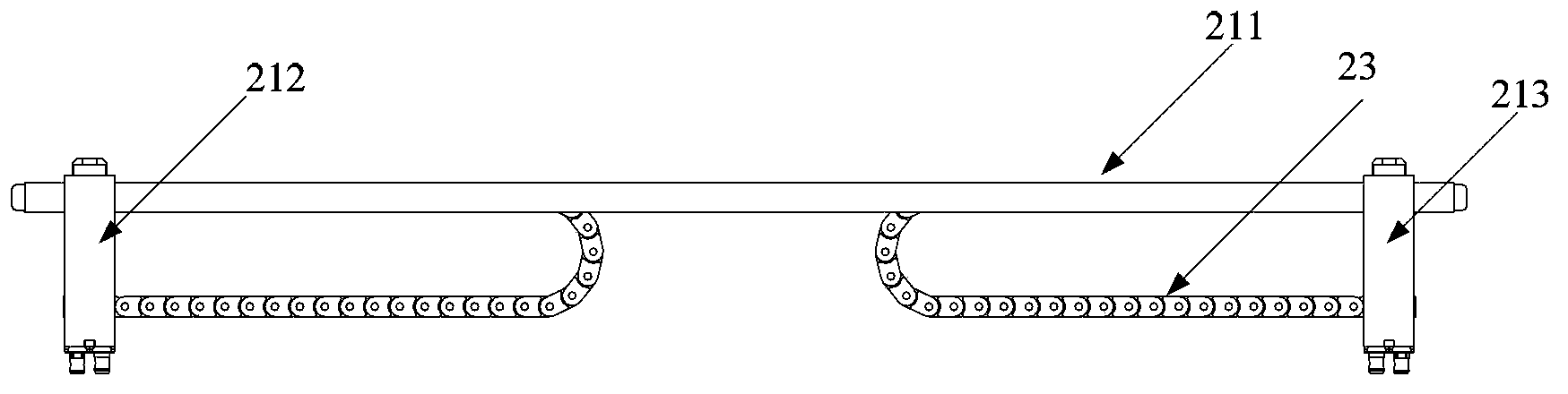
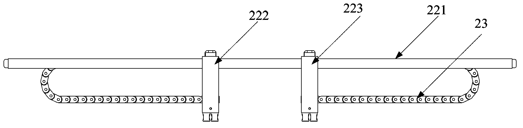
[0051]The fiber core butt connector 2 fixed on the butt plate 1, the fiber core butt connector includes: several parallel line connectors 21 and several parallel rope connectors 22, wherein, as figure 2 As shown, the line connector 21 includes: a first sliding bar 211, a first line fiber core connector 212 and a second line fiber core connector 213 that can slide along the first sliding bar 211, and the first line fiber core connector 213 can slide The input end and the output end of a line fiber core connector 212 are connected by connecting optical fibers, and the input ends and output ends of the second line fiber core connector 213 are connected by connecting optical fibers; image 3 As shown, th...

Embodiment 2

[0068] The basic structure of the optical fiber core butt connector provided by the embodiment of the present invention is basically similar to the structure in the first embodiment, the difference is that, as Figure 8 As shown, the docking device also includes: a plurality of arc-shaped holes 12 distributed along the circumferential direction of the docking hole 11, and the two ends of the arc-shaped holes 12 are away from the docking hole 11 along the arc-shaped hole 12. and a plurality of protrusions 13 located on the inner wall of the docking hole 11 and arranged opposite to the arc-shaped hole 11 along the radial direction of the arc-shaped hole 12, the protrusions 13 and the The arc holes 12 correspond one to one.

[0069] Preferably, the arc-shaped holes 12 are evenly distributed in the circumferential direction of the butt holes 11 . More preferably, the number of the arc-shaped holes 12 is four, but this is not limited in the present invention.

[0070] Since the s...

Embodiment 3

[0073] The basic structure of the optical fiber core butt joint equipment provided by the embodiment of the present invention is basically similar to the structure in the first embodiment, the difference is that, as Figure 9 As shown, the fiber core connector includes: a connecting part 91; a fixing part 92, the fixing part 92 is provided with a cavity 921 passing through its left and right sides, and the bottom of the cavity 921 is provided with two through Hole 922, the through hole 922 penetrates through the fiber core connector; two fiber core link flanges 93, one end of the fiber core link flange 93 is fixed in the through hole 922, and the other One end is provided with a second cylindrical portion 933 for fixing the external access fiber core, and at least one fiber core connection flange 93 is provided with a transparent stepped hole 931 inside. Specifically, the fiber core connecting flange 93 is composed of a concentric first cylindrical portion 932 and a second cyl...


PUM


Abstract

An embodiment of the invention discloses an optical fiber core butt joint device. The optical fiber core butt joint device comprises a butt joint board, an optical fiber core butt joint connector and a mechanical arm, wherein the optical fiber core butt joint connector comprises a plurality of line connectors parallel to one another and a plurality of rope connectors parallel to one another, each line connector comprises a first sliding rod, a first line fiber core connector and a second line fiber core connector, the input end and the output end of each first line fiber core connector are connected with each other through a connection optical fiber, and the input end and the output end of each second line fiber core connector are connected with each other through a connection optical fiber; each rope connector comprises a second sliding rod, a first rope fiber core connector and a second rope fiber core connector, wherein each first rope fiber core connector is connected with each second rope fiber core connector through a connection optical fiber. By means of the optical fiber core butt joint device, automatic butt joint of different line optical fibers in an optical fiber network can be achieved, operation is simple, a great amount of manpower and material resources are saved, and work efficiency is improved.

Description

technical field [0001] The invention relates to the technical field of optical fiber communication, in particular to an optical fiber core butt joint device. Background technique [0002] With the rapid development of power grid construction and the continuous improvement of the automation of power system equipment, the optical fiber power communication network has also achieved unprecedented development. [0003] At present, as the basic bearer network of optical fiber communication transmission - optical fiber network, its operation and maintenance work is still in the original manual mode, that is, it usually needs to manually go to the site to perform fiber jumping operations to realize the docking exchange between different optical fibers. However, due to the geographical dispersion, cumbersome manual switching operations and many other factors, such manual operations in daily life are huge and time-consuming. Therefore, how to realize the automatic docking and exchange...

Claims


Application Information

Patent Timeline
IPC IPC(8): G02B6/38
CPCG02B6/3508G02B6/3558G02B6/3574G02B6/3806G02B6/3809H04Q2011/0024
Inventor 李鹏仇钧朱承治徐志强汤亿则章力伟
Owner STATE GRID CORP OF CHINA
Why Eureka
Try Eureka