Optical loop device and photoelectric oscillator based on optical loop energy storage and filtering

A technology of photoelectric oscillators and optical splitters, applied in masers, solid-state lasers, circuits, etc., can solve problems such as signal quality degradation, difficulty in realizing single-mode oscillation, and inability to overcome the influence of optical fiber on ambient temperature

Active Publication Date: 2015-07-22
THE 44TH INST OF CHINA ELECTRONICS TECH GROUP CORP
View PDF3 Cites 0 Cited by
  • Summary
  • Abstract
  • Description
  • Claims
  • Application Information

AI Technical Summary

Problems solved by technology

[0005] First of all, for long optical fibers, there are two problems: one is that it brings spurs and deteriorates the signal quality; the other is that it is seriously affected by the ambient temperature;
[0006] In general, increasing the length of the optical fiber can effectively increase the energy storage time of the optoelectronic oscillator, thereby reducing the phase noise of the signal, but in order to obtain a signal with extremely low phase noise, it can only be achieved by greatly increasing the length of the optical fiber, which makes While obtaining low phase noise, the length of the fiber has reached the order of kilometers, so that the intrinsic longitudinal mode interval of the photoelectric oscillator will be reduced to the order of tens of kHz. Due to the influence of the performance of the microwave filter, the microwave filter is in the The filter passband bandwidth of the high-frequency band is on the order of tens of MHz, so it is difficult to achieve single-mode oscillation, and the side-mode oscillation will bring spurs, thereby degrading the quality of the generated signal; in order to solve this problem, research The personnel proposed to use a double-ring or multi-ring structure. While ensuring low phase noise and increasing the distance between the longitudinal modes, the side modes can be suppressed to a certain extent. Although this structure can solve the spurious problem to a certain extent, it does not It is impossible to overcome the problem that the optical fiber is affected by the ambient temperature, because when the ambient temperature changes, the effective refractive index of the optical fiber will also change, so that the eigenmode of the oscillation ring cavity will change, resulting in a change in the frequency of the generated microwave / millimeter wave signal Drift; especially when the optical fiber is long, any slight change in the ambient temperature will be very obvious in the frequency drift
[0007] In addition, for an optoelectronic oscillator that uses an optical resonator to form a high-Q energy storage medium, in order to generate a signal with low phase noise, the optical resonator is required to have a very high Q value; this requires the optical resonator. The sidewall has extremely low roughness, usually on the order of nanometers; this places extremely high requirements on the manufacturing process of optical resonators, which is very difficult to achieve
And even if such a process is realized, the roughness of the side wall of the optical resonator reaches the order of nm, and the phase noise of the generated microwave / millimeter wave signal is still high. The phase noise of the signal generated by the oscillator is 20~30dB higher than that of the optical oscillator based on long optical fiber

Method used


Image

  • Optical loop device and photoelectric oscillator based on optical loop energy storage and filtering
  • Optical loop device and photoelectric oscillator based on optical loop energy storage and filtering
  • Optical loop device and photoelectric oscillator based on optical loop energy storage and filtering

Examples


Embodiment Construction

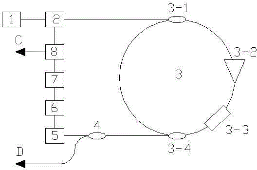
[0059] A photoelectric oscillator based on optical loop energy storage and filtering, the photoelectric oscillator is composed of a pumping light source 1, an electro-optic modulator 2, an optical loop device 3, an optical splitter 4, a photodetector 5, a microwave A filter 6, a microwave amplifier 7 and a microwave power divider 8 are formed;

[0060] The optical splitter one 4 is a single-input double-output mode, and the two output terminals are respectively recorded as output terminal one and output terminal two, and the splitting ratio of output terminal one and output terminal two is 90:10;

[0061] The interrelationships between the aforementioned components are:

[0062] The pump light source 1 is connected to the input end optical path of the electro-optic modulator 2; the output end of the electro-optic modulator 2 is connected to the input end optical path of the optical loop device 3; the output end of the optical loop device 3 is connected to the optical splitter-...


PUM


Abstract

Provided is an optical loop device and a photoelectric oscillator based on optical loop energy storage and filtering. An optical loop with a relative short optical fiber length is applied by the optical loop device to realize energy storage. After the optical loop is used for forming the photoelectric oscillator, a high-quality signal is obtained and usage of optical fibers in the photoelectric oscillator is reduced simultaneously. The beneficial effects of the invention are that: the photoelectric oscillator with high performance is provided, a problem in the prior art that optical fiber length needed to realize low noise may reach kilometer magnitude is solved, sensitivity of the photoelectric oscillator to temperature change is reduced, inhibition effect is effectively performed on starting vibration of side formwork and thus stray is eliminated.

Description

technical field [0001] The invention relates to a photoelectric oscillator, in particular to an optical loop device and a photoelectric oscillator based on optical loop energy storage and filtering. Background technique [0002] Oscillators are important core devices in signal transmitting or receiving systems. They have been widely used in communication, radar, signal processing, radio astronomy, sensing, measurement and other technologies involving the generation, reception and processing of electromagnetic wave signals. In some demanding application requirements, the oscillator is required to be able to generate signals with high frequencies such as X-band and Ka-band and ultra-low phase noise. [0003] Conventional oscillators are quartz crystal oscillators and atomic clocks. They can generate ultra-low phase noise signals with the help of high-Q oscillation modes, but their signal frequencies are only a few MHz to hundreds of MHz. To generate higher frequency signal...

Claims


Application Information

Patent Timeline
Patent Type & Authority Patents(China)
IPC IPC(8): H01S1/00H01S1/02
Inventor 张羽孙力军
Owner THE 44TH INST OF CHINA ELECTRONICS TECH GROUP CORP
Why Eureka
Try Eureka