A filter group for fluids

A fluid filter and filter group technology, which is applied in the fields of dispersed particle filtration, gas treatment, chemical instruments and methods, etc., can solve problems such as the ineffective utilization of tubular filter membranes

Inactive Publication Date: 2013-12-11
UFI INNOVATION CENT
View PDF3 Cites 1 Cited by
  • Summary
  • Abstract
  • Description
  • Claims
  • Application Information

AI Technical Summary

Problems solved by technology

[0011] In this known configuration, the tubular filter membranes 16, 18 are not well utilized in the area close to the inlet duct 12, whereas filtration normally takes place in the area 34, 18 of the membranes 16, 18 close to the outlet duct 14. within 36

Method used


Image

  • A filter group for fluids
  • A filter group for fluids
  • A filter group for fluids

Examples


Embodiment Construction

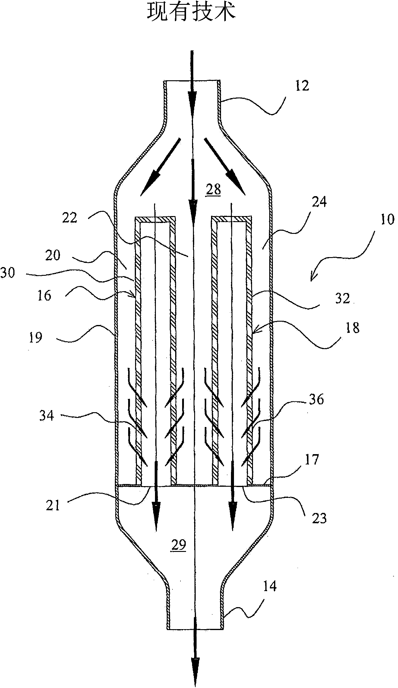
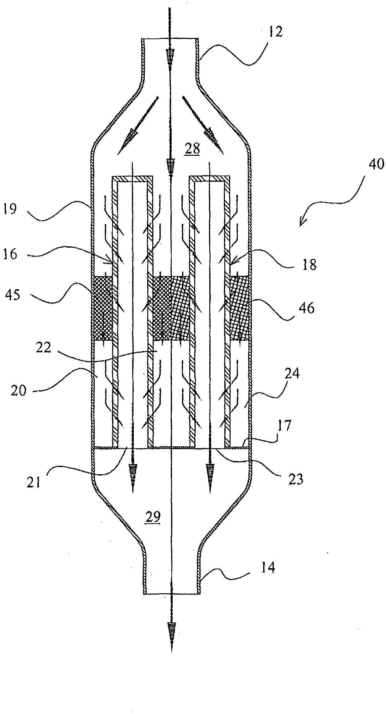
[0031] figure 2 An axial flow fluid filter 40 is shown comprising a generally tubular housing 19 providing an inlet conduit 12 for fluid to be filtered and an outlet conduit 14 for filtered fluid.

[0032] A perforated plate (perforated at 21 and 23) is arranged inside the housing 19, on which there are tubular filter membranes 16, 18 which extend parallel to the axis of the housing 19 and which The internal volume of the body is divided into two chambers 28, 29, of which the first chamber 28 communicates with the inlet conduit 12 for the fluid to be filtered and the second chamber 29 communicates with the outlet conduit 14 for the filtered fluid.

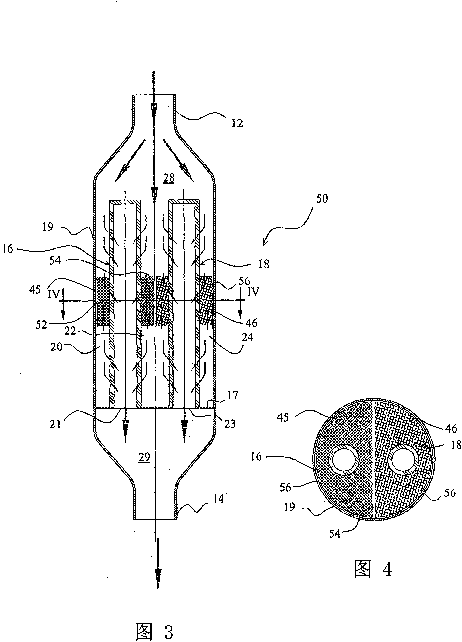
[0033] The fluid to be filtered thus enters the volumes 20, 22, 24 of the first chamber 28 which pass the fluid through the filter membrane. In one embodiment of the invention, the axial flow filter 40 includes pressure distributors 45 , 46 inside the chamber 28 .

[0034] In more detail, a pressure distributor 45, 46 is located...


PUM


Abstract

A filter group (40) for fluids, comprising an external casing (19) having any section, suitable for receiving at least a filter membrane (16, 18) which develops parallel to the axis of the casing (19), for dividing an internal volume of the casing (19) into two chambers (28, 29), of which a first chamber (28) is in communication with an inlet conduit (12) for the fluid to be filtered and a second chamber (29) is in communication with an outlet conduit (14) of the filtered fluid. At least a pressure distributor element (45, 46) is provided for each of the filter membranes and is accommodated in the first chamber (28), which at least a pressure distributor (45, 46) axially separates the volume of the first chamber (28) into at least two parts, the pressure distributor element being made of a material that is permeable to the flow of fluid to be filtered, wherein the pressure distributor (45, 46) for each of the filter membranes is located in an intermediate position on the respective membrane and is configured to increase the pressure differential on the upstream parts of the filter elements (16, 18).

Description

technical field [0001] The present invention relates to a fluid filter set. [0002] In particular, the set can be used for filtering fluids such as air or gases in various applications, including those in the automotive sector. Background technique [0003] In the filtration of combustion air in internal combustion engines it is customary to include a filter bank comprising a housing divided into two parts by a filter membrane perpendicular to the main flow direction. In these systems, depending on the choice of vessel shell geometry, the pressure drop across the filter membrane is more or less constant across its entire surface. [0004] On the other hand, in the use of tangential filters (ie, filters with a filter surface parallel to the fluid flow), the pressure differential along the length of the filter element is not constant. [0005] In a tangential filter, a generally cylindrical housing is divided into two parts by a plate perpendicular to the axis and located ...

Claims


Application Information

Patent Timeline
Patent Type & Authority Applications(China)
IPC IPC(8): B01D53/22B01D63/06
CPCB01D46/2407B01D46/446B01D2313/08B01D2313/26B01D2313/90B01D2258/06B01D2259/4566B01D53/22
Inventor G·吉隆迪
Owner UFI INNOVATION CENT
Why Eureka
Try Eureka