
torsion beam suspension

A technology of torsion beam suspension and trailing arm, which is applied in the direction of suspension, elastic suspension, interconnection system, etc., can solve the problems of weight increase and large size of trailing arm torsion beam suspension, so as to reduce rigidity and realize Effects of weight reduction and suppression of moment force

Inactive Publication Date: 2015-11-25
FUTABA IND CO LTD
View PDF8 Cites 0 Cited by
  • Summary
  • Abstract
  • Description
  • Claims
  • Application Information

AI Technical Summary

Problems solved by technology

In order to ensure the required rigidity, the size of the trailing arm 100, etc. and the torsion beam suspension will be increased, and the weight will increase.

Method used


Image

  • torsion beam suspension
  • torsion beam suspension
  • torsion beam suspension

Examples


Embodiment Construction

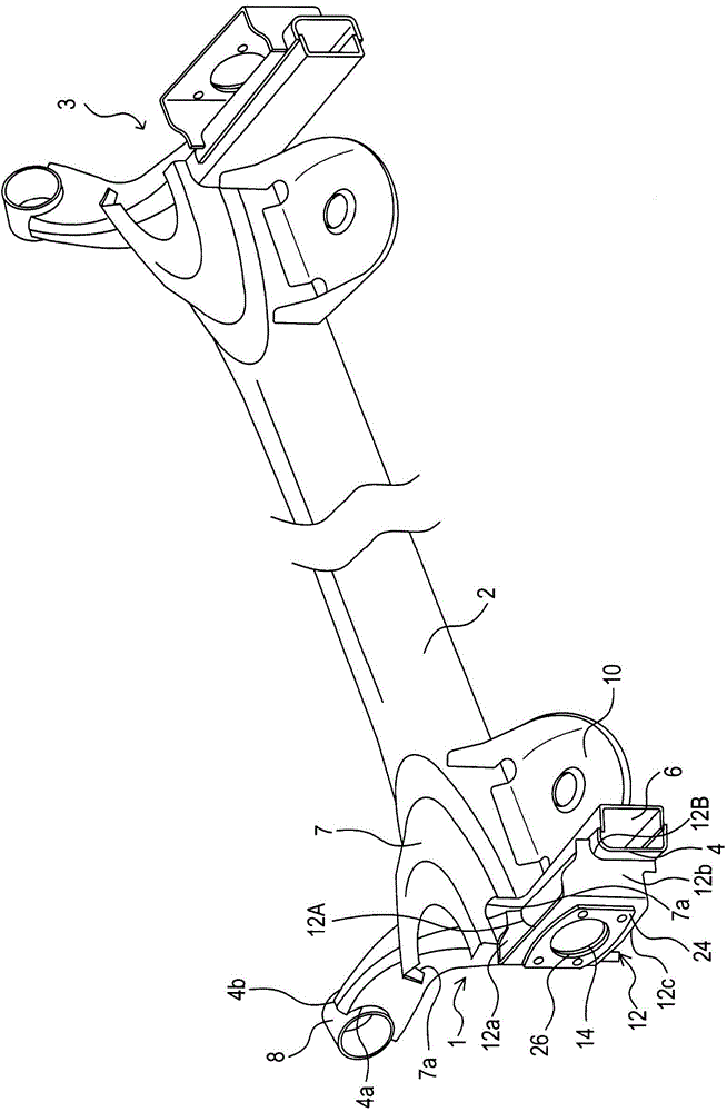
[0033] Such as figure 1 As shown, the torsion beam type suspension of this embodiment is formed by connecting the left trailing arm 1 and the right trailing arm 3 through the torsion beam 2 . Trailing arm 1 and trailing arm 3 are left and right symmetrical. The trailing arms 1 and 3 are formed in a hollow shape.

[0034] The torsion beam 2 is disposed between the trailing arms 1 and 3, and the two ends of the torsion beam 2 are welded to the trailing arms 1 and 3 respectively. Since the torsion beam type suspension of this embodiment is bilaterally symmetrical, in this specification, the trailing arm 1 on the left will be described as a center.

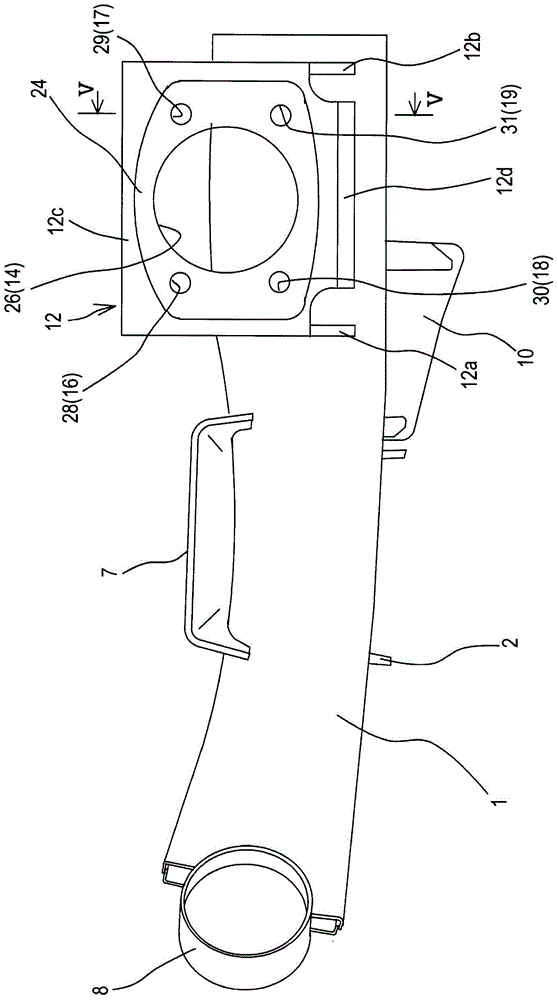
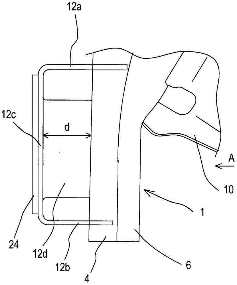
[0035] Such as figure 1 , Figure 5 As shown, the trailing arm 1 is formed by butting a pair of arm members 4 and 6 that can be divided in the width direction of the vehicle body along the axial direction of the trailing arm 1 .

[0036] The pair of arm members 4 and 6 are each formed by press molding so that the cross-sectiona...


PUM


Abstract

Provided is a torsion beam suspension for a vehicle that includes a left-right pair of trailing arms, each trailing arm being supported at one end thereof by a vehicle body and having at the other end thereof a carrier fixed thereto, via which a wheel is supported; and a torsion beam that connects the trailing arms to each other. The carrier has a plurality of fastening holes formed therein, into which fastening members are inserted to mount to the carrier a wheel support member. The plurality of fastening holes are arranged such that some of the plurality of fastening holes overlap the trailing arm as viewed from an axial direction of an axle shaft. In the trailing arm, tool insertion holes are formed in a penetrating manner so as to be positioned approximately coaxially with the fastening holes.

Description

[0001] Cross References to Related Applications [0002] This international application claims priority from Japanese Patent Application No. 2011-16836 filed at the Japan Patent Office on January 28, 2011, the entire contents of which are incorporated herein by reference. technical field [0003] The present invention relates to a torsion beam type suspension in which left and right trailing arms are connected by a torsion beam. Background technique [0004] A torsion beam type suspension in which left and right trailing arms are connected by a torsion beam is widely known. For example, as described in Patent Document 1, the left and right trailing arms and the torsion beam are connected by welding. A support is fixed to the other end of the trailing arm by welding, via which support the wheel is rotatably supported. The support member is bent to have a U-shaped cross section. Also, a mounting wall is formed on the supporting member. A plurality of fastening holes are fo...

Claims


Application Information

Patent Timeline
Patent Type & Authority Patents(China)
IPC IPC(8): B60G9/04
CPCB60G21/051B60G2206/20
Inventor 相马和刚森冈佳弘广谷敏次一柳荣成
Owner FUTABA IND CO LTD
Learn More