
Opposite punching type cutting knife base

A cutter seat and hedging technology, which is applied in the field of stamping devices, can solve the problems of large structure, cumbersome operation, and single function, and achieve the effects of broad market space, simple implementation, and simple manufacture

Active Publication Date: 2015-05-20
XIANGYANG FURUITE MACHINERY MFG CO LTD
View PDF5 Cites 0 Cited by
  • Summary
  • Abstract
  • Description
  • Claims
  • Application Information

AI Technical Summary

Problems solved by technology

[0003] The purpose of the present invention is to overcome the shortcomings of the current known stamping devices, such as large structure, single function, cumbersome operation, etc., and provide the public with a unique stamping die base product

Method used


Image

  • Opposite punching type cutting knife base
  • Opposite punching type cutting knife base
  • Opposite punching type cutting knife base

Examples


Embodiment Construction

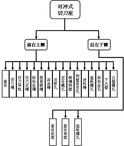
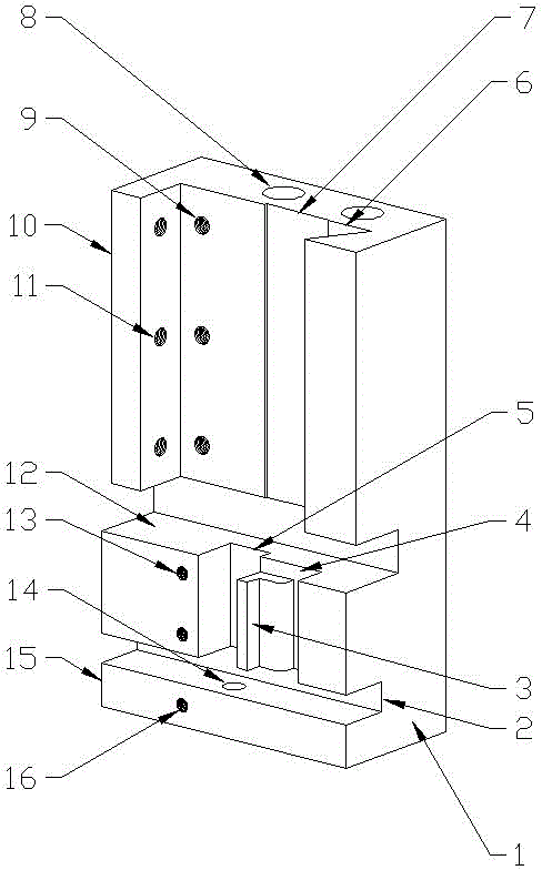
[0030] As a technical proposal for product manufacturing, the present invention can make the proposal concretely implemented through the organic combination of corresponding organizational structures. The product organization structure of an embodiment of the present invention is as follows: figure 1 shown.

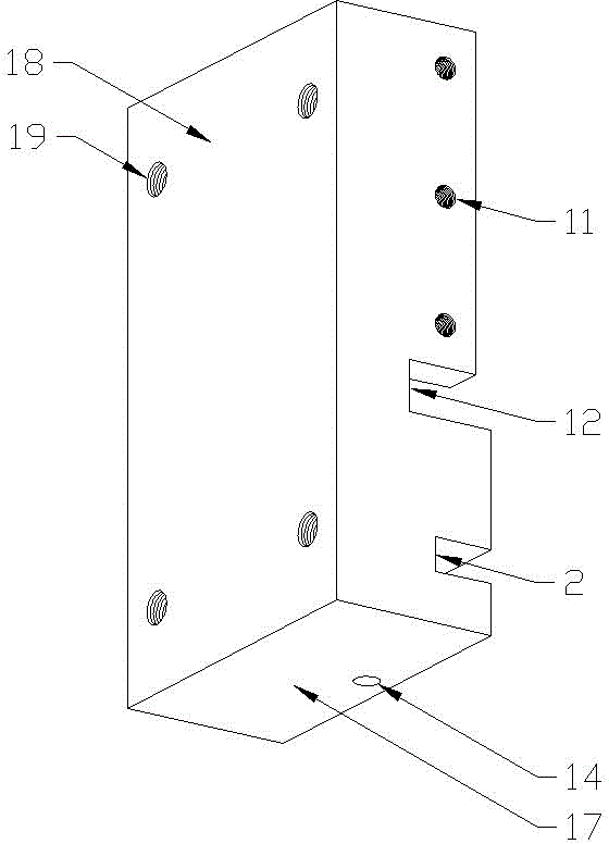
[0031] figure 1 Among them, the product is composed of two modules on the front right upper side and the rear left lower side. Among them, the front upper right module includes the base body, the top knife groove, the cutter guide rail, the cutter sinker groove, the discharge seat groove, the dovetail wedge groove, the lubricating groove, Pressure plate hole, bead screw hole, wedge groove side wall, side wall fastening hole, feeding trough, cover plate screw hole, discharge seat hole, lower convex wall, convex wall screw hole sixteen components, the rear left lower side module It includes three components: the bottom surface of the base body, the back side of the base b...


PUM


Abstract

The invention relates to a punching device, in particular to an opposite punching type cutting knife base without independently splitting an upper die base and a lower die base. A product comprises a front upper right module and a back lower left module, wherein the front upper right module comprises 16 constituents including a base body, a top knife groove, a cutting knife guide rail, a cutting knife sinking groove, a discharge seat groove, a dovetail wedge groove, a lubricant oil groove, a pressure plate hole, a wedge groove sidewall, a sidewall fastening hole, a feed groove, a discharge seat hole, a lower convex wall and the like, and the back lower left module comprises 3 constituents including a bottom surface of the base body, a base plate screw hole and the like. The product overcomes the defects of huge structure, single function, complicated operation and the like of a conventional punching device, and provides the punching die base product with capable and vigorous structure, specific effect, safety and reliability for the public, furthermore, the opposite punching type cutting knife base has the advantages of simple implementation and simple manufacturing, and the formed product has attractive appearance of the structure, stability and durability, wide market space, and higher industrial application value and economic additional value.

Description

technical field [0001] The invention relates to a stamping device, in particular to a counter-type cutter seat which does not need to separate the upper die seat and the lower die seat separately. Background technique [0002] Stamping device, commonly known as "punch machine", refers to a processing machine that uses stamping methods to form metal plates or punch holes in metal plates. Currently known stamping devices, whether the processing purpose is cutting, edge trimming, tongue cutting, cutting, reverse drawing, punching center hole, punching, punching, punching, punching, or flaring, embossing, pressing Embossing, embossing, forming, smooth blanking, twisting, thinning and deep drawing, curling, curling, drawing, drawing, bending, deep drawing, bulging, bending, differential temperature drawing, sectioning, undulating forming, Leveling, hydraulic deep drawing, deep hole punching, blanking, chisel cutting, fine blanking, shrinking, shaping, trimming, turning holes, an...

Claims


Application Information

Patent Timeline
Patent Type & Authority Patents(China)
IPC IPC(8): B21D28/14
Inventor 郑小玲
Owner XIANGYANG FURUITE MACHINERY MFG CO LTD
Learn More