Reconstructable tool

A mold and module technology, applied in the field of reconfigurable molds, can solve the problems of difficult to achieve rapid conversion of different surfaces, high cost control system cost, high control system requirements, etc., to achieve simple structure, low cost, and avoid stuck. Effect

Inactive Publication Date: 2013-12-18
NINGBO UNIV
View PDF6 Cites 13 Cited by
  • Summary
  • Abstract
  • Description
  • Claims
  • Application Information

AI Technical Summary

Problems solved by technology

However, the moldless multi-point forming device for sheet metal has the following problems: 1. The forming device is composed of upper and lower basic body groups, an adjustment mechanism and a loading mechanism, and there are many components in each component, and the structure is too complicated, which is not conducive to assembly and maintenance, and the requirements for the control system are very high, the cost of the whole device and the cost of the control system are very high; 2. Use the adjustment mechanism to adjust each punch one by one, and the process of adjusting one is also very complicated, resulting in the entire device. The adjustment time is very long, the efficiency is low, and it is difficult to achieve fast conversion between different surfaces

Method used


Image

  • Reconstructable tool
  • Reconstructable tool
  • Reconstructable tool

Examples


Embodiment 1

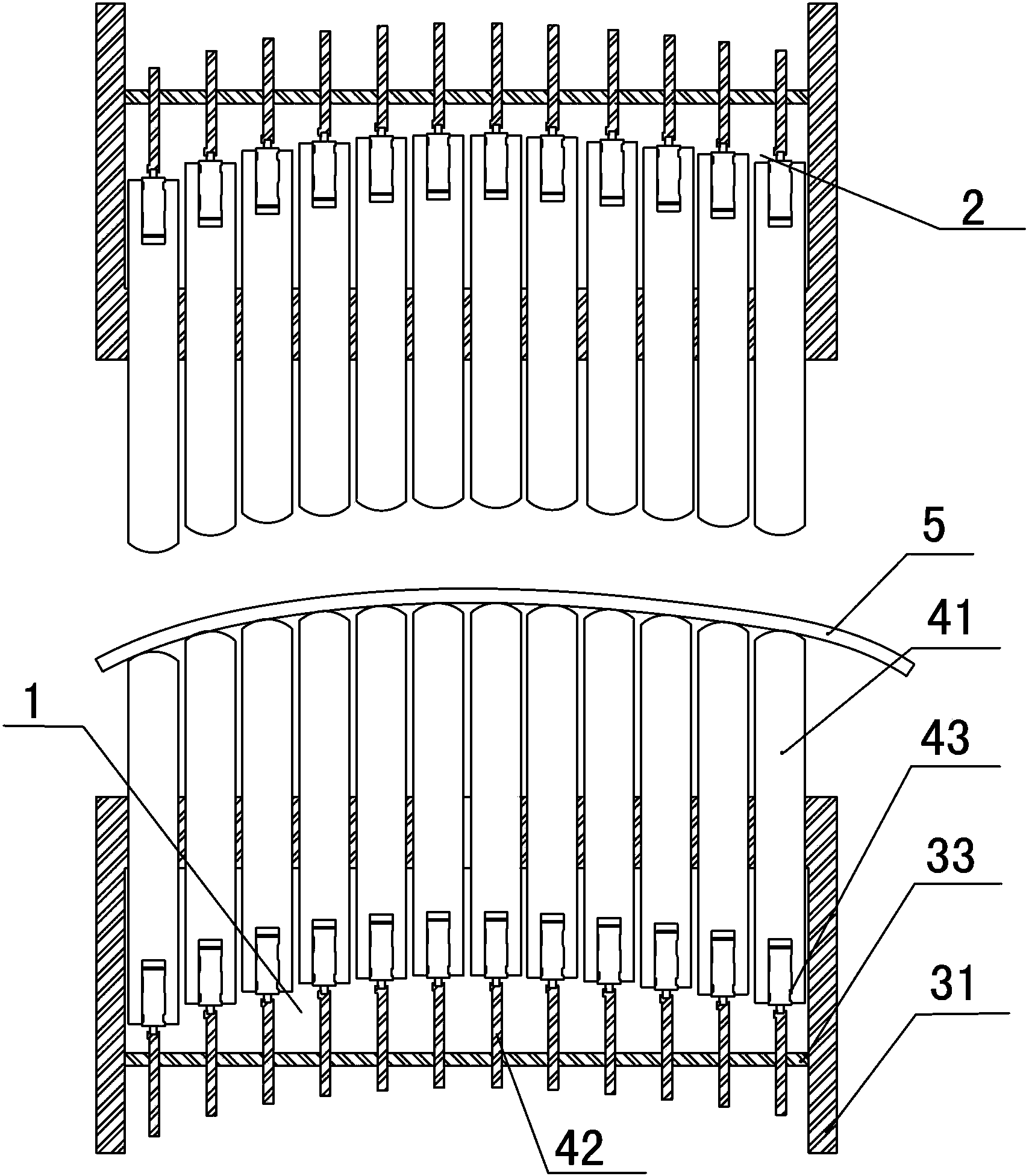
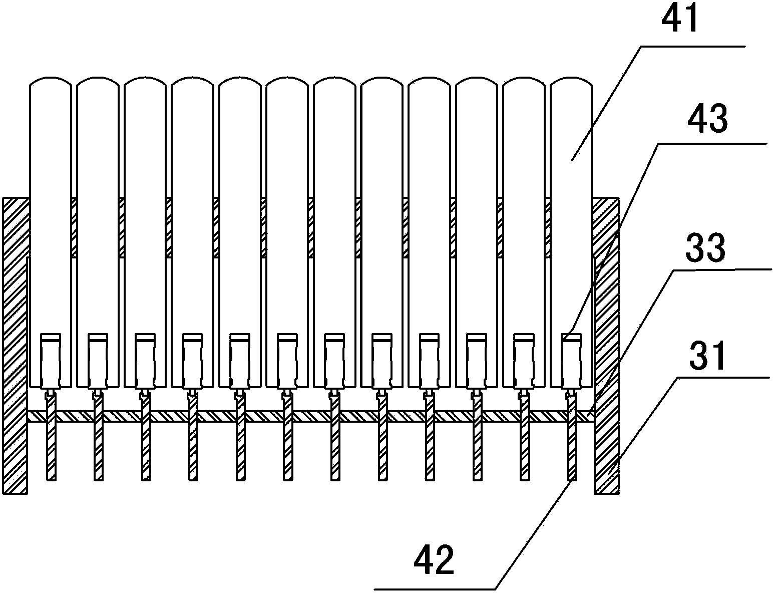
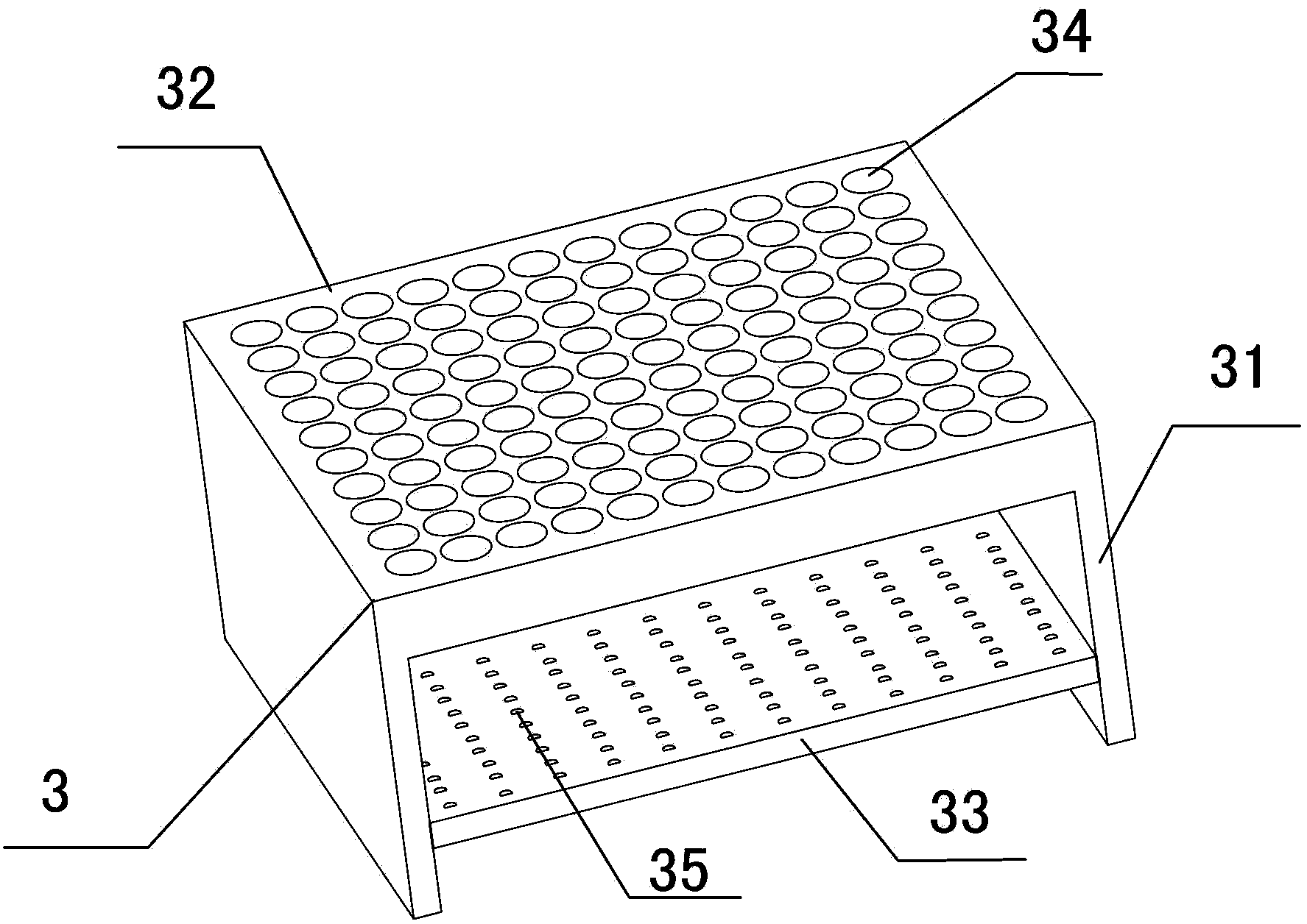
[0022] Embodiment one: if Figure 1~6 As shown, a reconfigurable mold includes a first module 1 and a second module 2 arranged symmetrically up and down, the first module 1 includes a base 3 and a plurality of reconfiguration units 4, and the base 3 includes a bracket 31 , the base plate 32 and the limiting plate 33, the base plate 32 and the limiting plate 33 are respectively fixed on the support 31, the base plate 32 is provided with a plurality of threaded holes 34, the limiting plate 33 is provided with a plurality of limiting holes 35, a plurality of The threaded holes 34 correspond coaxially to a plurality of limit holes 35. Each reconstruction unit 4 includes a screw 41, a guide rod 42 and a small motor 43. The motor body 431 of the small motor 43 is embedded in the tail of the screw 41. The screw 41 The tail end is provided with the stopper 44 of fixing small-sized motor 43, and the afterbody of screw rod 41 is threadedly connected with threaded hole 34, and the motor ...

Embodiment 2

[0028] Embodiment two: if Figure 7 As shown, a reconfigurable mold includes a first module 1 and a second module 2 symmetrically arranged left and right, the first module 1 includes a base 3 and a plurality of reconfiguration units 4, and the base 3 includes a bracket 31 , the base plate 32 and the limiting plate 33, the base plate 32 and the limiting plate 33 are respectively fixed on the support 31, the base plate 32 is provided with a plurality of threaded holes 34, the limiting plate 33 is provided with a plurality of limiting holes 35, a plurality of The threaded holes 34 correspond coaxially to a plurality of limit holes 35. Each reconstruction unit 4 includes a screw 41, a guide rod 42 and a small motor 43. The motor body 431 of the small motor 43 is embedded in the tail of the screw 41. The screw 41 The tail end is fixedly provided with the block 44 of fixing small-sized motor 43, and the afterbody of screw rod 41 is threadedly connected with threaded hole 34, and the...


PUM


Abstract

The invention discloses a reconstructable tool comprising a first module and a second module. The first module comprises a base and a plurality of reconstructable units. The base comprises a support, a base plate and a limit plate, wherein the base plate and the limit plate are fixed on the support, the base plate is provided with a plurality of threaded holes, the limit plate is provided with a plurality of limit holes, and the threaded hole are in coaxial one-to-one correspondence to the limit holes. Each reconstructable unit comprises a screw, a guide bar and a small motor, wherein a motor body of the small motor is embedded in the tail of the screw, the tail end of the screw is provided with a stopper used for fixing the small motor, the tail of the screw is in threaded connection with the one threaded hole, a motor shaft of the small motor extends out of the tail of the screw and is fixedly connected with the guide bar, and the guide bar locating in the corresponding limit hole matches with the corresponding limit hole in shape. The reconstructable tool has the advantages that the structure is simple, the cost is low, different surfaces can be changed fast, and the efficiency is high.

Description

technical field [0001] The invention relates to a mold, in particular to a reconfigurable mold. Background technique [0002] At present, the important parts of aircraft, automobiles, ships, power generation equipment, chemical containers and many equipment in the military field are usually curved parts with multiple curved surfaces (complex curved surfaces). When preparing these curved surface parts, stamping technology is generally used to form them complex surfaces. However, when stamping technology is used, the curved parts are equipped with special molds, and the molds of each curved part are usually specific, that is, one curved part corresponds to one mold. Any small modification of the curved surface parts may lead to the scrapping of the mold, requiring redesign and machining of a new mold, resulting in a lot of waste. [0003] In order to solve the above problems, Chinese invention patent No. ZL00110773.9 discloses a dieless multi-point forming device for plates....

Claims


Application Information

Patent Timeline
Patent Type & Authority Applications(China)
IPC IPC(8): B21D37/02
Inventor 刘建辉李国平王彦王志坚
Owner NINGBO UNIV
Why Eureka
Try Eureka