Clamping device of steel belt discharging support

A technology of clamping device and discharging rack, which is applied to the attachment of shearing machines, shearing devices, metal processing equipment, etc., and can solve the problems of affecting the cutting effect, excessive feeding speed of the steel strip, and scratches on the surface of the steel strip and other problems, to achieve the effect of convenient production, improve work efficiency and reduce labor intensity

Inactive Publication Date: 2013-12-18
TAIZHOU HUINENG STAINLESS STEEL PROD
View PDF0 Cites 4 Cited by
  • Summary
  • Abstract
  • Description
  • Claims
  • Application Information

AI Technical Summary

Problems solved by technology

[0004] The present invention provides a clamping device for a steel strip unwinding rack, which has a reasonable design and solves the problem that the steel strip unwinds too fast, causing scratches on the surface of the steel strip and affecting the cutting effect, reduces the labor intensity of the staff and improves work efficiency

Method used


Image

  • Clamping device of steel belt discharging support

Examples


Embodiment Construction

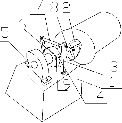
[0012] Below in conjunction with accompanying drawing, the present invention will be described in further detail:

[0013] Such as figure 1 Shown: a clamping device for a steel belt discharge rack in this embodiment, including a discharge rack 1, a clamping device is arranged on the discharge rack 1, and the clamping device includes an adjusting disc 2, a support rod 3, Semicircular clamp block 4, bearing 6, connecting rod 7, spring 8, resistance gasket 9.

[0014] The bearing 6 is welded and fixed on the rotating shaft 5 on the discharge rack 1, the left and right ends of the bearing 6 are provided with a semi-circular clamp block 4, and a resistance gasket 9 is fixed on the semi-circular clamp block 4. 。

[0015] Each semicircular ring clamp block 4 is fixed on the support rod 3, and the bottom of each support rod 3 is linked and fixed on the support platform of the discharge rack 1, between the two support rods 3 The connecting rod 7 is connected and fixed, wherein one e...


PUM


Abstract

The invention discloses a clamping device of a steel belt discharging support. The clamping device comprises the discharging support, and the clamping device is arranged on the discharging support. The clamping device comprises an adjusting disc, support rods, semicircular clamping blocks, a bearing and a connection rod. The bearing is fixedly welded on a rotating shaft of the discharging support, the semicircular clamping blocks are arranged at the left end and the right end of the bearing, each semicircular clamping block is fixed on a corresponding support rod, the bottom of each support rod is fixedly connected onto a support table of the discharging support, the two support rods are fixedly connected through the connection rod, threads are arranged at one end of the connection rod, and the adjusting disc is fixed on the connection rod through the threads. The clamping device has the advantages of effectively controlling discharging speed, facilitating shearing of a steel belt through a shearing machine, being reasonable in design and convenient to manufacture, reducing labor intensity of workers and improving working efficiency.

Description

technical field [0001] The invention relates to a clamping device for a steel belt discharging rack. Background technique [0002] At present, the steel strips made of stainless steel products are cut according to the specifications and sizes required by customers. Generally, the wound and bundled steel strips are placed on the steel strip discharge rack, and the steel strip is sent to the cutting machine through the steel strip discharge rack. tailoring. [0003] Generally, the feeding speed cannot be controlled, and the cutting effect is often affected by the excessive feeding. When the cutting machine stops working, the feeding continues due to inertia, which brings great trouble to the staff, and the steel belt cannot be delivered in time. The cutting machine will fall on the ground due to friction and cause scratches on the surface of the steel strip, causing losses to the enterprise. Contents of the invention [0004] The present invention provides a clamping devi...

Claims


Application Information

Patent Timeline
Patent Type & Authority Applications(China)
IPC IPC(8): B23D33/02
Inventor 朱增军
Owner TAIZHOU HUINENG STAINLESS STEEL PROD
Why Eureka
Try Eureka