Energy-saving elevator bank with traction machine driving two lift cars

A technology for a traction machine and an elevator group, applied in the field of elevators, can solve the problems of complex elevator structure, high cost, troublesome elevator structure maintenance, etc., and achieve the effects of reducing energy consumption, improving safety, and saving waiting time.

Inactive Publication Date: 2013-12-18
罗湘林
View PDF4 Cites 1 Cited by
  • Summary
  • Abstract
  • Description
  • Claims
  • Application Information

AI Technical Summary

Problems solved by technology

[0008] 2. The structure of the elevator is complicated and the cost is high
[0009] 3. Complex elevator structure causes maintenance troubles

Method used


Image

  • Energy-saving elevator bank with traction machine driving two lift cars

Examples


Embodiment 1

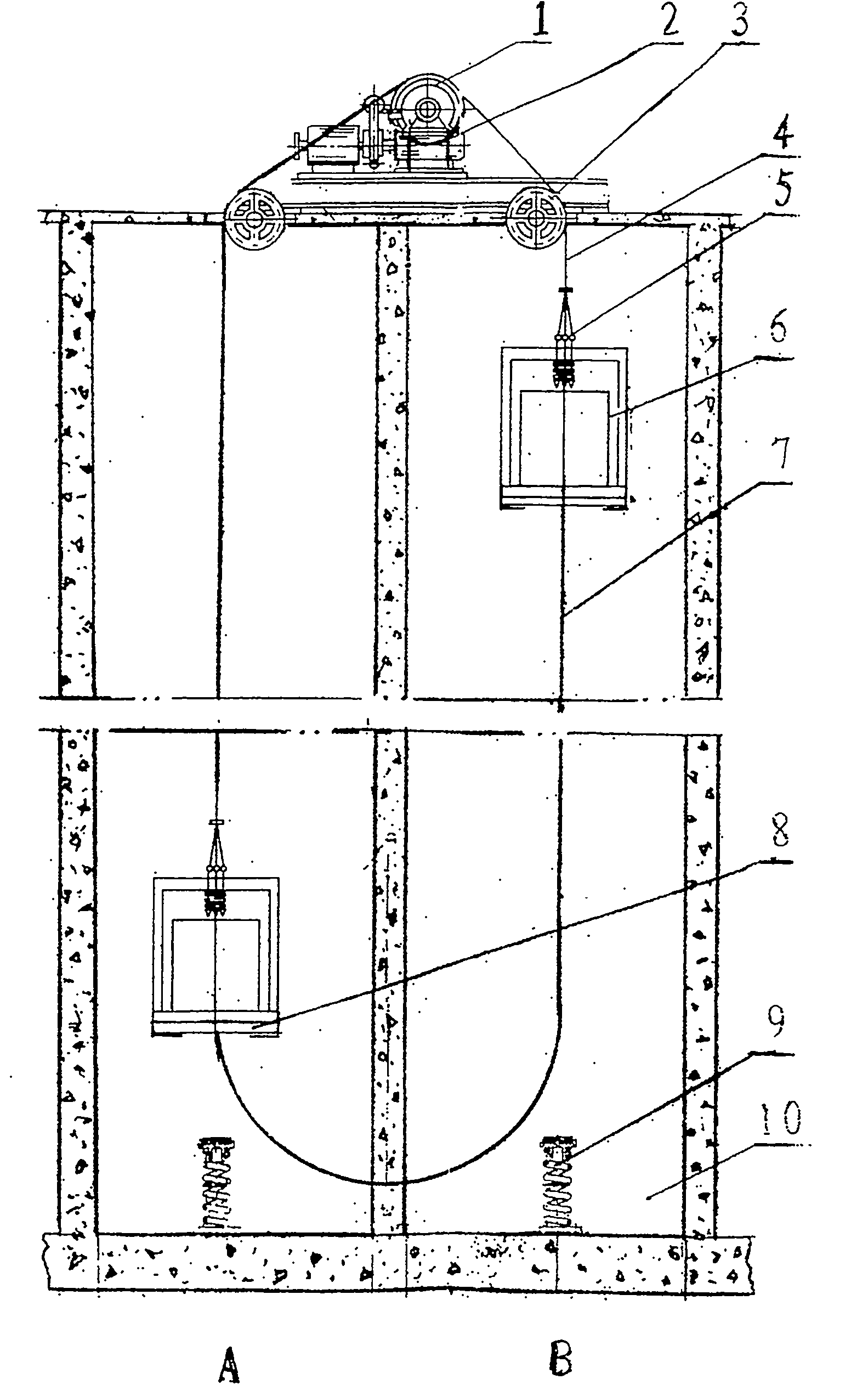
[0045] Two energy-saving elevator groups are set side by side in the middle of the 30-story office building. Each energy-saving elevator group is equipped with adjacent elevator A and elevator B, a total of 4 hoistways 10 and 4 working cars 6. Each car has a 6-carrying capacity of 1,000 kg and a rated capacity of 14 passengers. On the upper part of the partition wall between the elevator A and the elevator B, there is a traction machine 2. A traction sheave 1 is arranged on the traction machine 2. The traction sheave 1 is connected with a traction rope 4, and two of the traction ropes 4 The ends are respectively connected to the tops of the elevator cars 6 of elevator A and elevator B through guide wheels 3; there are two guide wheels 3, which are respectively arranged on the upper part of the hoistway 10 of elevator A and elevator B and the lower part of the traction machine 2. Compensating counterweights 8 are provided at the lower part of the car 6 of elevator A and elevato...

Embodiment 2

[0047] A 10-storey office building, with 2 energy-saving elevator groups in the middle, and different departmental offices before and after the elevator group. Each energy-saving elevator group is equipped with elevator A and elevator B with the car door facing away. There are 4 hoistways 10 and 4 working cars 6. Each car has a 6-carrying capacity of 1,000 kg and a rated capacity of 14 passengers. In the upper part of the partition wall in the hoistway 10 of elevator A and elevator B, a traction machine 2 is provided. The traction machine 2 is provided with a traction sheave 1 connected to the traction sheave 1 with a traction wire rope 4, and both ends of the traction wire rope 4 are connected to the tops of the elevator cars 6 of the elevator A and elevator B through guide wheels 3, respectively. There are two guide wheels 3, which are respectively arranged on the upper part of the hoistway 10 of the elevator A and the elevator B, and the lower part of the traction machine ...


PUM


Abstract

The invention discloses an energy-saving elevator group with a traction machine driving two lift cars and belongs to elevator technologies in order to solve the problem that an existing elevator is huge in power consumption, high in cost and troublesome in maintenance. The energy-saving elevator group comprises an elevator A and an elevator B which are adjacent. The traction machine (2) is arranged between upper portions of shaftways (10) of the elevator A and the elevator B, a traction sheave (1) is disposed on the traction machine (2) and connected with a traction steel rope (4), and two ends of the traction steel rope (4) are respectively connected with the tops of the elevator A and the elevator B through two guide wheels (3). The guide wheels (3) are respectively arranged on the upper portions of the shaftways (10) of the elevator A and the elevator B and on the lower portion of the traction machine (2). The lower portion of the lift car (6) of each of the elevator A and the elevator B is provided with a compensating counterweight filler (8). The bottoms of the lift cars (6) of the elevator A and the elevator B are connected with two ends of a compensate chain (7) respectively. The energy-saving elevator group has the advantages of being low in energy consumption, short in waiting time and low in cost.

Description

Technical field [0001] The present invention belongs to elevator technology, and specifically is an energy-saving elevator group in which one traction machine drives two cars. Background technique [0002] Elevator is a mechatronics, highly intelligent vertical transportation tool, and an indispensable lifting and transportation tool in modern society. Since the German inventor Siemens invented the elevator, the elevator has a wide range of applications due to its convenient use and fast lifting speed, which can quickly raise and lower people and goods in space. With the development of urbanization, a large number of high-rise buildings appear, and the use of elevators is increasing. According to incomplete statistics in 2012, the country has 1.7 million elevators, and Shanghai alone has 165,000 elevators. There are so many tall buildings in modern cities that cannot exist and develop without elevators. Elevators can be divided into passenger elevators, freight elevators, pass...

Claims


Application Information

Patent Timeline
Patent Type & Authority Applications(China)
IPC IPC(8): B66B11/08
Inventor 罗湘林张文杰严鸿韦
Owner 罗湘林
Why Eureka
Try Eureka