
Serial two-way throttling stub pipe mechanism and throttling method thereof

A short-throttle tube and two-way throttling technology, which is applied to refrigerators, mechanical equipment, fluid circulation arrangements, etc., can solve the problems of increasing production costs, increasing the probability of welding joint leakage, one-way valve noise, etc., and reducing welding joints , remarkable technical effect and application value, and the effect of avoiding vibration and noise

Inactive Publication Date: 2016-03-23
SOUTH CHINA UNIV OF TECH
View PDF5 Cites 0 Cited by
  • Summary
  • Abstract
  • Description
  • Claims
  • Application Information

AI Technical Summary

Problems solved by technology

The main problem with this structure is that a one-way valve is added to the throttling device, which not only increases the production cost, but also increases the probability of welding joint leakage and the possibility of noise generated by the one-way valve

Method used


Image

  • Serial two-way throttling stub pipe mechanism and throttling method thereof
  • Serial two-way throttling stub pipe mechanism and throttling method thereof

Examples


Embodiment

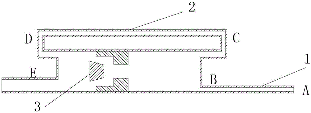
[0031] figure 1 It is a structural schematic diagram of the prior art.

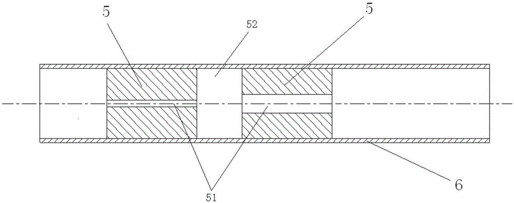
[0032] figure 2 It is a structural schematic diagram of the serial bidirectional throttle short tube mechanism of the present invention. The present invention includes a metal pipe 6, and a multi-stage throttling spool spool 5 axially arranged in the metal pipe 6 at intervals; the space between each section of the choke short pipe spool 5 forms a flash gas-liquid chamber 52 ;

[0033] The axes of the refrigerant passages 51 of each throttle short tube spool 5 are coaxial with the axes of the metal pipe 6;

[0034] The inner diameter of the refrigerant flow channel 51 from the throttle short tube spool 5 at the initial end to the throttle short tube 51 at the end gradually increases;

[0035] When the air-conditioning system is cooling, the refrigerant enters from the throttle short tube spool 5 at the initial end, and then flows out from the throttle short tube spool 5 at the end;

[0036] When the ...


PUM


Abstract

The invention discloses a serial two-way throttling stub pipe mechanism and a throttling method thereof. The serial two-way throttling stub pipe mechanism comprises a metal pipe and a plurality of sections of throttling stub pipe valve elements axially arranged in the metal pipe at intervals. The space between every two adjacent sections of throttling stub pipe valve elements forms a flash vapor and liquid cavity. The axis of a refrigerant flow channel of each section of throttling stub pipe valve element coincides with the axis of the metal pipe. The inner diameters of the refrigerant flow channels of the throttling stub pipe valve elements are gradually increased from the throttling stub pipe valve element at the initial end to the throttling stub pipe valve element at the tail end. When an air conditioning system carries out refrigerating, refrigerant enters from the throttling stub pipe valve element at the initial end and then flows out from the throttling stub pipe valve element at the tail end. When the air conditioning system carries out heating, the refrigerant enters from the throttling stub pipe valve element at the tail end and then flows out from the throttling stub pipe valve element at the initial end. By the adoption of the structure which is simple and convenient and easy to realize, it is unnecessary to install a one-way valve in an existing refrigerating and heating type air conditioner, and therefore production cost is lowered; welded junctions are reduced, and therefore leakage risks are reduced; vibration noise generated by a one-way valve is avoided.

Description

technical field [0001] The invention relates to a throttling mechanism of an air-conditioning system, in particular to a series-type two-way throttling short pipe mechanism and a throttling method thereof. Background technique [0002] In cooling and heating air conditioners, due to the different operating conditions of cooling and heating, the refrigerant flow requirements are different under the two operating modes. Heating is achieved by flowing through different capillary lengths. Usually used in the design figure 1 Structure. When the air conditioner is cooling, the refrigerant flows in from the A end of the main capillary tube 1, opens the one-way valve 3, and flows directly through the one-way valve 3 without going through the auxiliary capillary tube 2 to the E end. When heating, the refrigerant flows in from the E end, and the one-way valve 3 is closed. Due to the blocking effect of the one-way valve, the refrigerant enters the auxiliary capillary tube 2 through ...

Claims


Application Information

Patent Timeline
Patent Type & Authority Applications(China)
IPC IPC(8): F25B41/06F25B41/38
CPCF25B41/30
Inventor 汪双凤刘腾庆徐言生张新强周遊
Owner SOUTH CHINA UNIV OF TECH
Learn More