Thin type flat rectilinear vibration motor

A linear vibration, flat technology, applied in electrical components, electromechanical devices, etc., can solve the problems of complex design, inconvenient replacement, poor universality, etc.

Inactive Publication Date: 2013-10-02
JINLONG MACHINERY & ELECTRONICS CO LTD
View PDF6 Cites 5 Cited by
  • Summary
  • Abstract
  • Description
  • Claims
  • Application Information

AI Technical Summary

Problems solved by technology

[0010] For this reason, the technical problem to be solved by the present invention is to overcome the defect that the installation structure of the vibration motor in the prior art causes the coil terminal to be welded with the main board of the user end to cause inconvenient replacement, thereby providing a vibration motor that can be replaced when the vibration motor is damaged. It is not necessary to replace the thin flat linear vibration motor of the user-side motherboard at the same time
[0011] Another technical problem to be solved by the present invention is to overcome the problem of poor universality in manufacturing caused

Method used


Image

  • Thin type flat rectilinear vibration motor
  • Thin type flat rectilinear vibration motor
  • Thin type flat rectilinear vibration motor

Examples


Embodiment Construction

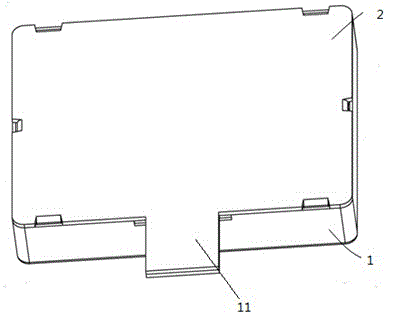
[0038] such as 1 and figure 2 As shown, this embodiment provides a vibration motor, including a casing 1 and a cover plate 2 mounted on the casing 1, the casing 1 has a bottom surface 14, and a first side wall 12 connected to the bottom surface 14 , the second side wall 13, the front wall 15 and the rear wall (not shown in the figure), the bottom surface 14 and the above-mentioned side wall of the casing 1 enclose a cavity with a specific height, and the front wall 15 is provided with The concave mounting groove 11, the cover plate 2 has an outwardly protruding cover plate protrusion 21, and the cover plate protrusion 21 is inserted into the concave mounting groove 11, so that the cover plate 2 and the The casings 1 are assembled together to form an installation space.

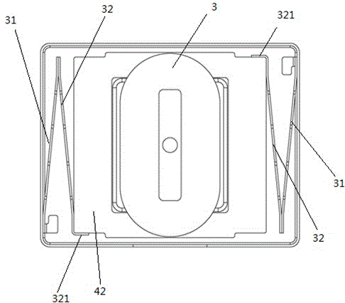
[0039] In the installation space, a vibration block 41, a permanent magnet 42, a coil 5, and an insulating support plate 6 are sequentially installed from the casing 1 toward the cover plate 2, and the vibra...


PUM

PropertyMeasurementUnit
Densityaaaaaaaaaa

Abstract

The invention provides a thin type flat rectilinear vibration motor which comprises a casing, a cover plate covering the casing and forming mounting space with the casing, and a vibration assembly hung inside the mounting space through being positioned by elastic support pieces positioned on the two opposite side walls of the casing, wherein the vibration assembly comprises a vibration block and permanent magnets mounted on the vibration block, and can perform reciprocating vibration in the direction roughly parallel to the bottom surface of the casing under the action of the magnetic field force; a coil is mounted above the permanent magnets at the specific clearance position away from the permanent magnets inside the mounting space; an insulation support plate is mounted at the upper part of the coil, and is provided with a lug boss protruding out of the mounting space from the side surface; a wiring terminal in plug-in connection with a main board of a user terminal is mounted on the lug boss; a conducting wire is pre-buried inside the insulation support plate; one end of the conducting wire is electrically connected with the leading wire end of the coil, and the other end of the conducting wire is electrically connected with the wiring terminal.

Description

technical field [0001] The invention relates to a vibrating motor, in particular to a thin flat linear vibrating motor used in portable consumer electronic products. Background technique [0002] Currently, mobile consumer electronics products on the market generally use vibration motors as system feedback components, for example, mobile phone call notifications, game console vibration feedback, and so on. Existing vibration motors on the market mainly include cylindrical iron core motors, hollow cup motors and flat motors. The structure of the cylindrical iron core motor and the coreless motor has many disadvantages such as complex mechanism, thick motor, many manufacturing processes, complicated process, large motor noise and poor control accuracy. Nowadays, in order to meet the design requirements of thin, light and portable electronic consumer products, vibration motors are gradually developing in the direction of flat, light and thin. [0003] A linear vibration motor...

Claims


Application Information

Patent Timeline
IPC IPC(8): H02K33/18
Inventor 金绍平方绍彬陈实张芮泽李中平
Owner JINLONG MACHINERY & ELECTRONICS CO LTD
Why Eureka
Try Eureka