Integrated permanent magnet speed regulating speed changer

A permanent magnet speed regulation and transmission technology, applied in electrical components, electromechanical devices, electromechanical transmission devices, etc., can solve problems such as mechanical fatigue, friction loss, vibration noise, poor heat dissipation effect, and inability to discharge in time, to increase heat dissipation capacity, Various structural forms, the effect of improving the service life

Inactive Publication Date: 2016-07-27
南京艾凌节能技术有限公司
View PDF7 Cites 6 Cited by
  • Summary
  • Abstract
  • Description
  • Claims
  • Application Information

AI Technical Summary

Problems solved by technology

But, because the rotational speed of the first permanent magnet rotor (4) and the second permanent magnet rotor (11) are the same, and transmit torque through the transmission shaft (3), the transmission shaft (3) will produce mechanical fatigue, friction loss, Vibration noise, etc.; at the same time, due to the installation of the drive shaft (3), the overall volume of the structure will be large, which cannot meet the installation requirements of a small space; The magnetic induction lines generate eddy currents and generate heat, which cannot be discharged in time, and the heat dissipation effect is poor

Method used


Image

  • Integrated permanent magnet speed regulating speed changer
  • Integrated permanent magnet speed regulating speed changer
  • Integrated permanent magnet speed regulating speed changer

Examples


Embodiment 1

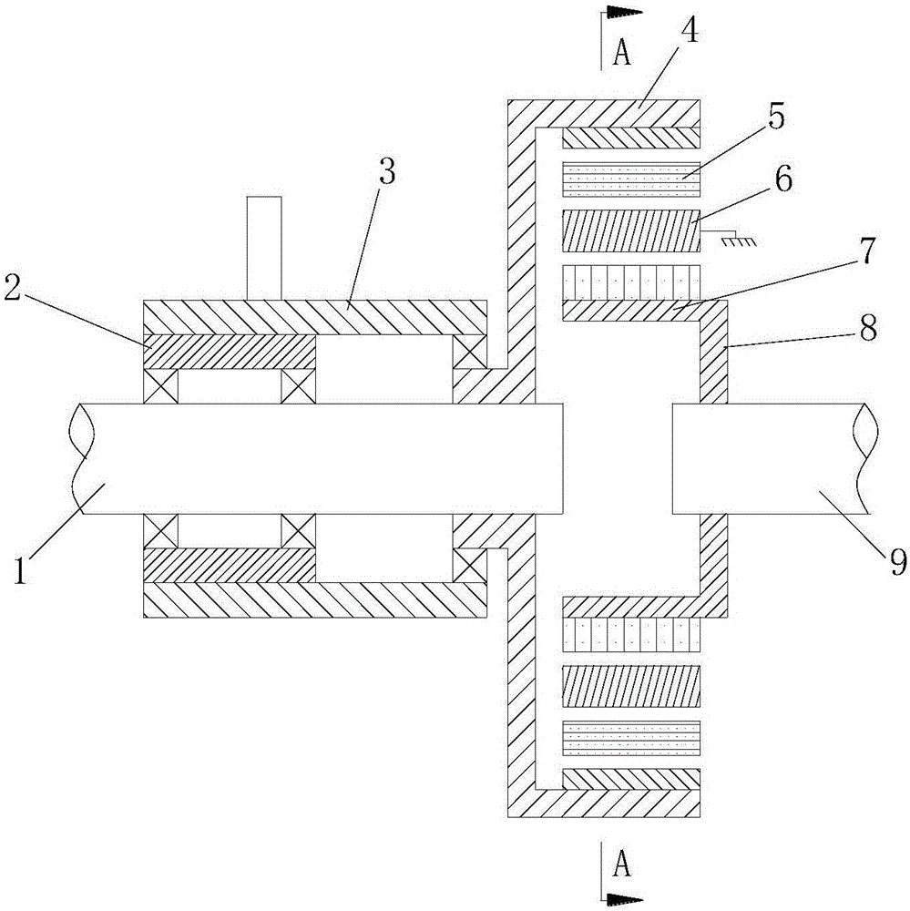
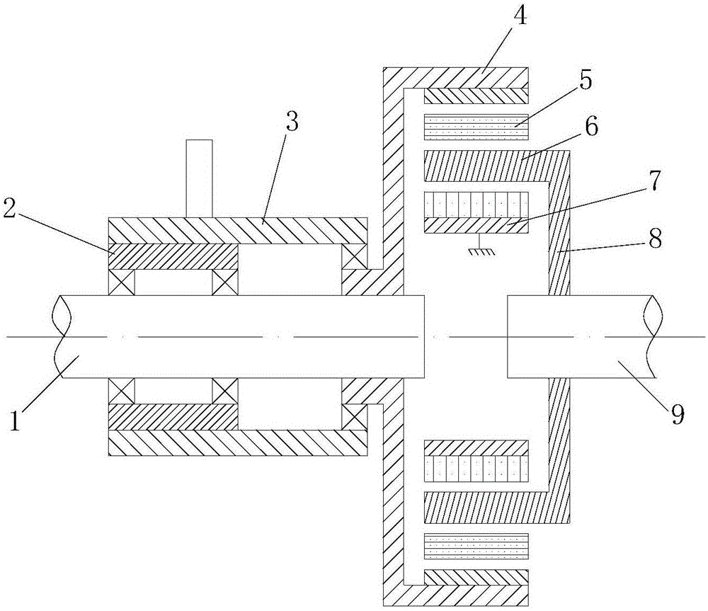
[0025] see figure 1 As shown, an integrated permanent magnet variable speed transmission includes an input shaft 1, a regulator 2, an adjusting rod 3, a conductor rotor 4, a first permanent magnet rotor 5, a modulation ring 6, a second permanent magnet rotor 7, and a flange 8. The output shaft 9 and the input shaft 1 are equipped with a conductor rotor 4 that rotates synchronously with the input shaft 1. The inner side of the conductor rotor 4 is sleeved with the first permanent magnet rotor 5, and the conductor rotor 4 drives the first permanent magnet rotor 5 to rotate through magnetic force. , the input shaft 1 is also provided with a regulator 2, the regulator 2 is connected with the conductor rotor 4 through the adjustment rod 3, by adjusting the regulator 2, the conductor rotor 4 is moved axially along the input shaft 1 to change the conductor rotor 4 and the first The relative area between the permanent magnet rotors 5, and then change the torque transmitted between the...

Embodiment 2

[0027] see figure 1As shown, an integrated permanent magnet variable speed transmission includes an input shaft 1, a regulator 2, an adjusting rod 3, a conductor rotor 4, a first permanent magnet rotor 5, a modulation ring 6, a second permanent magnet rotor 7, and a flange 8. The output shaft 9 and the input shaft 1 are equipped with a conductor rotor 4 that rotates synchronously with the input shaft 1. The inner side of the conductor rotor 4 is sleeved with the first permanent magnet rotor 5, and the conductor rotor 4 drives the first permanent magnet rotor 5 to rotate through magnetic force. , the input shaft 1 is also provided with a regulator 2, the regulator 2 is connected with the conductor rotor 4 through the adjustment rod 3, by adjusting the regulator 2, the conductor rotor 4 is moved axially along the input shaft 1 to change the conductor rotor 4 and the first The relative area between the permanent magnet rotors 5, and then change the torque transmitted between them...

Embodiment 3

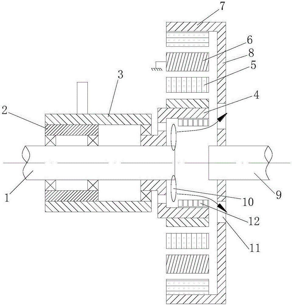
[0029] see image 3 As shown, an integrated permanent magnet variable speed transmission includes an input shaft 1, a regulator 2, an adjusting rod 3, a conductor rotor 4, a first permanent magnet rotor 5, a modulation ring 6, a second permanent magnet rotor 7, and a flange 8. The output shaft 9 and the input shaft 1 are equipped with a conductor rotor 4 that rotates synchronously with the input shaft 1. The outer side of the conductor rotor 4 is sleeved with a first permanent magnet rotor 5, and the conductor rotor 4 drives the first permanent magnet rotor 5 to rotate through magnetic force. , the input shaft 1 is also provided with a regulator 2, the regulator 2 is connected with the conductor rotor 4 through the adjustment rod 3, by adjusting the regulator 2, the conductor rotor 4 is moved axially along the input shaft 1 to change the conductor rotor 4 and the first The relative area between the permanent magnet rotors 5, and then change the torque transmitted between them ...


PUM


Abstract

The invention discloses an integrated permanent magnet variable speed transmission, which comprises an input shaft and an output shaft. A conductor rotor synchronously rotating with the input shaft is installed on the input shaft. A regulator is arranged on the input shaft. An adjustment rod is provided, and the regulator is connected to the conductor rotor through the adjustment rod. The corresponding position of the conductor rotor is provided with a first permanent magnet rotor, and the corresponding position of the first permanent magnet rotor is provided with a second permanent magnet rotor. A modulation ring is sleeved between the first permanent magnet rotor and the second permanent magnet rotor, any one of the modulation ring and the second permanent magnet rotor is fixed, and the other is fixedly connected to the output shaft through a flange Achieve power output. The invention has a variety of structural forms, and is suitable for speed-up and deceleration in various occasions; avoids mechanical fatigue, friction loss, vibration noise, etc., does not need to apply lubricating oil, and has high transmission efficiency; The heat is discharged in time, which improves the service life.

Description

technical field [0001] The invention belongs to the technical field of speed-adjusting transmissions, and relates to a speed-regulating and speed-changing mechanism, in particular to an integrated permanent magnet speed-adjusting transmission with exquisite structure and good heat dissipation performance. Background technique [0002] Most of the traditional transmission devices used between the prime mover and the working machine or the actuator are mechanical structures such as gear reducers or worm reducers. Due to the use of mechanical coordination for transmission, some irreversible problems will occur, such as mechanical fatigue , friction loss, vibration noise, etc. must be lubricated with lubricating oil to ensure the stability of mechanical movement, but after a long time, the sealing performance will be reduced due to mechanical vibration or wear, resulting in oil leakage. [0003] The existing alternative is to use magnetic gears. Since the magnetic transmission i...

Claims


Application Information

Patent Timeline
Patent Type & Authority Applications(China)
IPC IPC(8): H02K51/00
Inventor 王向东周丽萍
Owner 南京艾凌节能技术有限公司
Why Eureka
Try Eureka