Pile top crown beam structure of high-strength prestress pipe pile for supporting foundation pit and construction method thereof

A technology for prestressed pipe piles and foundation pit support, which is used in infrastructure engineering, excavation, construction, etc., can solve problems such as crown beams being easily pulled out, waste of reinforced concrete, etc. economic effect

Active Publication Date: 2013-12-18
WUHAN SURVEYING GEOTECHN RES INST OF MCC
View PDF7 Cites 7 Cited by
  • Summary
  • Abstract
  • Description
  • Claims
  • Application Information

AI Technical Summary

Problems solved by technology

[0004] Aiming at the current situation that the traditional method of high-strength prestressed pipe pile top crown beam will cause too much waste of reinforced concrete due to excessive anchoring into the hollow hole of the pipe pile and the crown beam is easy to be pulled out when the horizontal displacement of the pile top is uncoordinated. The present invention p

Method used


Image

  • Pile top crown beam structure of high-strength prestress pipe pile for supporting foundation pit and construction method thereof
  • Pile top crown beam structure of high-strength prestress pipe pile for supporting foundation pit and construction method thereof
  • Pile top crown beam structure of high-strength prestress pipe pile for supporting foundation pit and construction method thereof

Examples


Embodiment Construction

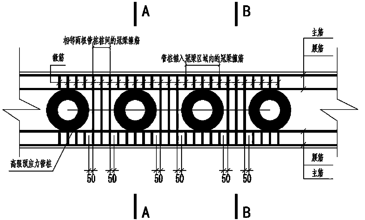
[0024] according to figure 1 , figure 2 , image 3 The pile top crown beam structure of a high-strength prestressed pipe pile used for foundation pit support is shown, and its structural characteristics are as follows:

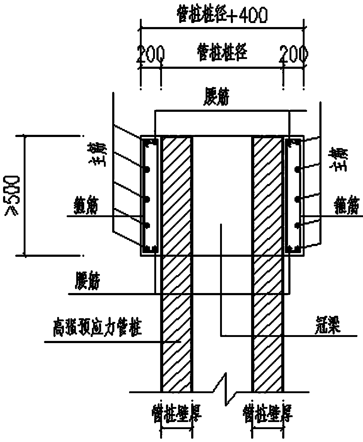
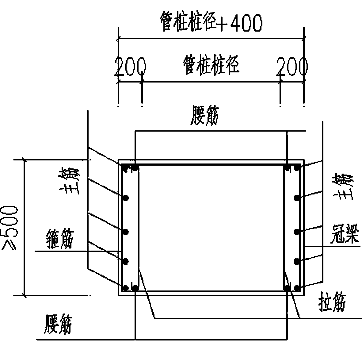
[0025] The crown beam is set on the top of the high-strength prestressed pipe pile, and the length of the high-strength prestressed pipe pile anchored into the crown beam is the same as the height of the crown beam; The waist bar of the beam is attached to the edge of the pipe pile; in the crown beam area between two adjacent high-strength prestressed pipe piles, a two-way two-leg hoop and two vertical tie bars are set, and the stirrup is 50mm away from the edge of the pipe pile ; In the crown beam area where the high-strength prestressed pipe pile is anchored into the crown beam, two independent two-way two-leg hoops are set.

[0026] The height of the crown beam is not less than 500mm, and the width is the pipe pile diameter + 400mm, that is, the edge of...


PUM

PropertyMeasurementUnit
Heightaaaaaaaaaa
Diameteraaaaaaaaaa
Strengthaaaaaaaaaa

Abstract

The invention relates to a pile top crown beam structure of a high-strength prestress pipe pile for supporting a foundation pit and a construction method thereof. The structure is characterized in that a crown beam is arranged at the tops of high-strength prestress pipe piles, the length of the part, inserted into the crown beam, of each high-strength prestress pipe pile is the same as the height of the crown beam, the height of the crown beam is not lower than 500mm, the width of the crown beam is 400mm more than the diameter of each pipe pile, the two ends of the crown beam respectively extend by 200mm out of the edge of each pipe pile, longitudinal stress reinforced bars of the crown beam are arranged near the edges of the inner side and outer side of the foundation pit, web bars are attached with the edge of each pipe pile, a bidirectional two-leg hoop bar and two additional vertical pull bars are arranged between the crown beams of the two adjacent high-strength prestress pipe piles, the hoop bar is 50mm away from the edge of each pipe pile, and two independent bidirectional two-leg bars are arranged in the area, anchored into the crown beam, of each high-strength prestress pipe pile. The method comprises the following steps of excavating earth to the bottom of the cushion layer of the crown beam, measuring and paying off, casting the cushion layer, binding the reinforced bars, supporting a formwork, casting concrete, airing water and curing, removing the formwork, and excavating the earth of the lower layer.

Description

technical field [0001] The invention relates to the technical field of deep foundation pit support engineering, in particular to a pile top crown beam structure and a construction method of high-strength prestressed pipe piles used for foundation pit support. Background technique [0002] As the urban land becomes more and more tense, in order to make full use of the existing land, the distance between the basement and the red line of the planned land is getting closer and closer, and the distance between some basements and the red line of the planned land is even less than 3m. Yes: a common foundation pit with a depth of 3~4m is restricted by the red line of the site, so simple support methods such as natural grading cannot be used, but vertical support structures must be used. At this time, high-strength prestressed pipe piles are used as a low-cost The supporting structure has wide application prospects. In order to make all the supporting pipe piles form a whole and pla...

Claims


Application Information

Patent Timeline
IPC IPC(8): E02D17/04
Inventor 陈斌丁洪元昌钰刘耀峰宁国立徐永刚刘军
Owner WUHAN SURVEYING GEOTECHN RES INST OF MCC
Why Eureka
Try Eureka