Thermostatic heat management power machine cooling system

A cooling system and power machine technology, applied in the direction of engine cooling, engine components, combustion engines, etc., can solve the problems of inability to control temperature and achieve excellent performance and good economical effect

Inactive Publication Date: 2013-12-18
湖北美标康盛动力科技有限公司
View PDF7 Cites 10 Cited by
  • Summary
  • Abstract
  • Description
  • Claims
  • Application Information

AI Technical Summary

Problems solved by technology

[0003] In order to overcome the deficiency that the existing power machine cooling system cannot control the two contradictory operating temperatures, the purpose of the present invention is to provide a constant temperature thermal management p

Method used


Image

  • Thermostatic heat management power machine cooling system

Examples


Embodiment Construction

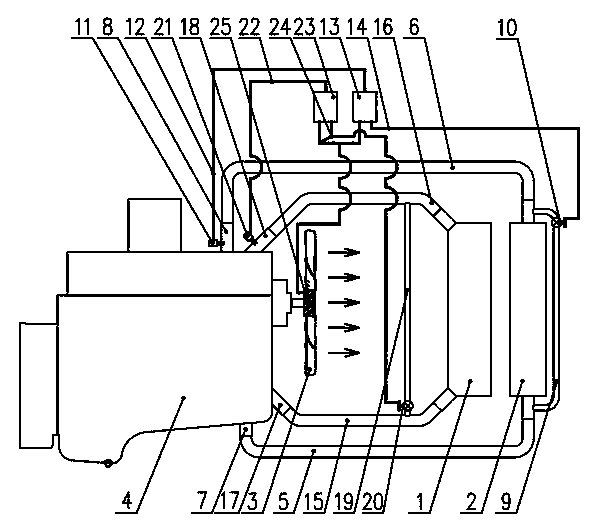
[0014] like figure 1 As shown, the supercharged air intake intercooler 1 of the present invention and the coolant radiator 2 are installed together in series, and the cooling fan 3 is installed on the engineering power machine 4 near the supercharged air intake intercooler 1 side.

[0015] The coolant radiator 2 is connected to the power machine water inlet 7 and water outlet 8 through the water inlet pipe 5 and the water outlet pipe 6, and the water inlet pipe 5 and the water outlet pipe 6 are connected through a bypass water pipe 9, and the coolant temperature control is installed in the bypass water pipe 9 An electronic proportional valve 10; a coolant temperature sensor 11 is installed at the water outlet 8 of the power machine, the coolant temperature sensor 11 is connected to the coolant temperature controller 13 through the wire harness 12, and the coolant temperature controller 13 is connected to the coolant temperature through the control wire harness 2 14 Temperature...


PUM


Abstract

The invention relates to the technical field of engineering power machines, in particular to a thermostatic heat management power machine cooling system. An air intake intercooler and a cooling liquid cooler are mounted in series, and a cooling fan is mounted on one side, close to the air intake intercooler, of the an engineering power machine. Through the arrangement that the intercooler and the cooling liquid cooler are mounted in series in a front-back manner, the fan mounted at the front end of the intercooler blows air towards the intercooler and the cooling liquid cooler to cool the same. Temperature sensors mounted on a water inlet and a water outlet of the power machine are used for monitoring an intake air temperature value and an outlet water temperature value; when the temperature values are lower than a required lower temperature limit, temperature controllers control a temperature-control electronic proportional valve on a bypass air pipe to be turned on according to temperature departure states to raise the temperature; when one temperature value is over an upper limiter, the corresponding temperature controller controls an electronic clutch to enable the fan to run so as to increase cooling air volume. Through control on different working conditions, the cooling liquid temperature and the boosting air intake temperature are kept within a required temperature range constantly, and thermostatic heat management on the power machine cooling system is realized.

Description

technical field [0001] The invention relates to the technical field of engineering power machines, in particular to a cooling system capable of performing constant temperature heat management on the cooling system of engineering power machines. Background technique [0002] At present, the known engineering power machine cooling system, through the rotation of the fan connected to the engine pulley, forms a cooling wind, blows through the cooling water tank and the intercooler connected in series or in parallel, and radiates heat to the cooling liquid of the power machine and the supercharged air intake. . Because the temperature control requirements of the power engine coolant are contrary to the temperature control requirements for the supercharged intake air of the power engine: the temperature of the coolant is required to be controlled between 92-97 degrees, and the closer the temperature is to the upper limit, the performance of the engine and fuel economy will be affe...

Claims


Application Information

Patent Timeline
IPC IPC(8): F01P7/16F01P7/02F02B29/04
CPCY02T10/12
Inventor 张辉
Owner 湖北美标康盛动力科技有限公司
Why Eureka
Try Eureka