Speed reducer structure

A technology of reducer and turbine shaft, which is applied in the direction of mechanical equipment, transmission parts, gear transmission, etc., can solve the problems of increased energy consumption, inaccurate positioning, and reduced rotation conversion rate, so as to improve energy utilization rate and ensure accurate efficiency, waste reduction effect

Inactive Publication Date: 2013-12-18
IMASS SANDER MFG SUZHOU
View PDF0 Cites 3 Cited by
  • Summary
  • Abstract
  • Description
  • Claims
  • Application Information

AI Technical Summary

Problems solved by technology

[0003] In order to solve the problems of poor coordination between the worm gear and the reducer in the existing reducer structure, inaccurate positioning when sw

Method used


Image

  • Speed reducer structure
  • Speed reducer structure

Examples


Embodiment Construction

[0019] The preferred embodiments of the present invention will be described in detail below in conjunction with the accompanying drawings, so that the advantages and features of the present invention can be more easily understood by those skilled in the art, so as to define the protection scope of the present invention more clearly.

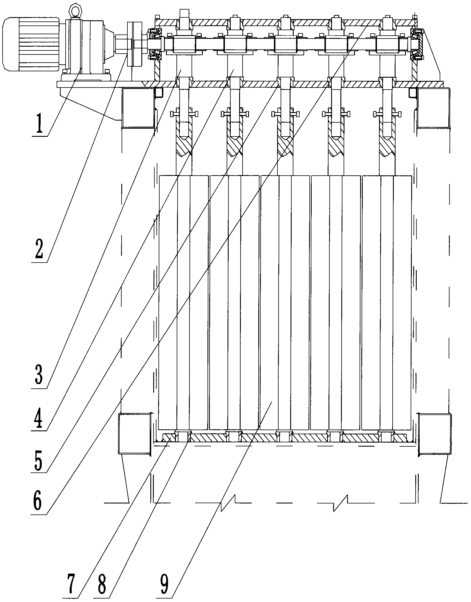
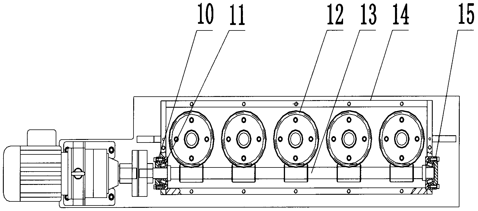
[0020] as attached figure 1 And attached figure 2 As shown, a reducer structure includes a box body 14, a box cover 6 placed on the top of the box body 14, a lower support plate 7 is installed at the bottom of the box body 14, and a transparent cover 10 is installed at the upper part of the box body 14, and the transparent cover A stuffy cover 15 is installed on the 10, a plurality of lower support plate sliding bearings 8 are installed on the lower support plate 7, a tapered roller bearing 11 is installed between the transparent cover 10 and the stuffy cover 15, and the coupling 2 is installed on the tapered roller Bearing 11, gear reduction m...


PUM


Abstract

The invention provides a speed reducer structure, which comprises a box body and a box cover arranged on the top of the box body, wherein a lower support plate is installed in the lower part of the box body; the upper part in the box body is provided with a transparent cover; the transparent cover is provided with a blank cover; the lower support plate is provided with a plurality of lower support plate sliding bearings; a cone roller bearing is installed between the transparent cover and the blank cover; a coupler is installed on the cone roller bearing; a gear speed reduction motor is connected to one end of the coupler; the other end of the coupler is connected with a worm; one ends of worm wheel shafts are installed on lower support plate sliding bearings on the lower support plate; the other ends of the worm wheel shafts are connected to the worm; the end parts of a lengthened worm wheel shaft and the worm wheel shafts are provided with worm wheels. According to the speed reducer structure disclosed by the invention, the worm wheels and the worm are meshed by insection, the worm is effectively driven by the speed reducer, so that the turnover number of the speed reducer is effectively lowered to the required turnover number so as to guarantee power transmission accuracy and high efficiency, the energy waste is reduced, and the energy use ratio is improved.

Description

technical field [0001] The invention relates to a reducer, in particular to a reducer structure with fast and accurate worm gear switching. Background technique [0002] The worm gear reducer is a power transmission mechanism that uses the speed converter of the gear to reduce the number of revolutions of the motor (motor) to the desired number of revolutions and obtain a larger torque. It can be seen in the transmission system of various machinery, from ships, automobiles, locomotives, heavy machinery used in construction, processing machinery and automatic production equipment used in the machinery industry, to common household appliances in daily life , clocks and more. Its application ranges from the transmission of large power to small loads. The precise angle transmission can be seen in the application of the reducer, and in industrial applications, the reducer has the function of reducing speed and increasing torque. The basic structure of the worm gear reducer is m...

Claims


Application Information

Patent Timeline
IPC IPC(8): F16H57/031F16H57/023F16H1/20
Inventor 申风浦险峰汪美娟
Owner IMASS SANDER MFG SUZHOU
Why Eureka
Try Eureka