Vehicle alternator

a vehicle alternator and battery technology, applied in the direction of engine starters, electric generator control, gearboxes, etc., can solve the problems of reducing the life of wear parts such as brushes, reducing the reliability of the vehicle alternator, and breaking rotating components, so as to reduce the stress of revolutions, increase the reliability of the vehicle alternator, and suppress the effect of the increase of the number of revolutions of the field magnet par

Inactive Publication Date: 2007-05-10
DENSO CORP
View PDF5 Cites 2 Cited by
  • Summary
  • Abstract
  • Description
  • Claims
  • Application Information

AI Technical Summary

Benefits of technology

[0016] It is possible to reduce revolution stress caused by centrifugal force and temperature rising stress caused by iron loss and the like in the vehicle alternator, and to increase the reliability of the vehicle alternator because the increase of the number of revolutions of the field magnet part can be suppressed by reducing the speed changing ratio “S” according to the increase of the number of revolutions of the engine. In addition, because this feature can eliminate the necessity to use high expensive components of high durability and anti-thermal resistance, the present invention provides the vehicle alternator at a low manufacturing cost. Further, because it is possible to set the speed changing ratio “S” to a high value during a low speed of revolution of the engine, it is thereby possible to keep adequate amount of the electric power generation in the low speed of revolution of the engine.
[0017] According to another aspect of the present invention, it is preferred to set the speed changing ratio “S” so that the number of revolutions of the field magnet part becomes a constant value when the number of revolutions of the engine exceeds a specified value. Because the magnitude of centrifugal force and the thermal stress to be applied to each component of the vehicle alternator is thereby reduced to a specified value or less, it is possible to prevent the excess amount of centrifugal force and the excess thermal stress applied to the vehicle alternator and possible to enhance the reliability of the vehicle alternator certainly.
[0018] Further, according to another aspect of the present invention, it is preferred to set the speed changing ratio “S” so that the number of revolutions of the field magnet part is reduced according to the increasing number of revolutions of the engine. It is thereby possible to reduce the centrifugal force and the thermal stress applied to each component of the vehicle alternator according to increasing the number of revolutions of the engine. In general, because the magnitude of vibration of the engine is increased according to increasing the speed of revolutions of the engine, it is possible to reduce the combination stress composed of vibration stress, centrifugal force stress, and thermal stress. This feature of the present invention further enhances the reliability of the vehicle alternator.
[0019] Still further, according to another aspect of the present invention, it is preferred to set the speed changing ratio “S” based on an instruction to be supplied from an external control unit mounted on a vehicle and separated from the vehicle alternator. It is thereby possible to set the speed changing ratio “S” based on the vehicle running state and the battery condition. As a result, because the electric power generation capability of the vehicle alternator can be freely changed, it is possible to design the minimum sized vehicle alternator while keeping the necessary amount of the electric power generation. The present invention can provide the vehicle alternator of a high reliability in a low manufacturing cost.
[0020] Furthermore, according to another aspect of the present invention, it is preferred to have the rotation speed changing part composed of a combination of a sun gear, planetary gears, an internal gear, and a driving mechanism. It is thereby possible to fix and operate the internal gear at a specified speed of revolution by the driving mechanism and possible to set the speed changing ratio “S” to a specified value.
[0021] In addition, according to another aspect of the present invention, it is preferred that the driving mechanism is an electric motor whose operation is controlled by an instruction transferred from the external control unit such as an engine control unit (ECU). It is thereby possible to easily control the number of revolutions of the internal gear in the rotation speed changing part by the electric motor and further to easily change the speed changing ratio “S” based on the operation of the electric motor controlled by the ECU.

Problems solved by technology

Accordingly, this means that it is necessary to keep a large amount of electric power in a vehicle alternator when the vehicle alternator is using a low speed of revolution.
However, although a high capability of electric power generation of the vehicle alternator is achieved on increasing the speed increasing ratio thereof as the former case, this manner decreases the lifetime of wear parts such as brushes and bearings which form the vehicle alternator, and further serves to break rotating components such as cooling fans because the vehicle alternator rotates at a high speed.
Thus, the vehicle alternator at a higher rotating speed causes various troubles such as thermal stress and wear stress, and those troubles decrease the reliability of the vehicle alternator.
If a vehicle alternator consists of various components of high reliability and durability in order to avoid those troubles and drawbacks, the manufacturing cost of the vehicle alternator is increased because the cost of each assembling components with high reliability and durability is generally high.
On the other hand, the latter case to increase the volume of the vehicle alternator brings to decrease or deteriorate the mounting flexibility of a vehicle and to introduce the difficulty of designing the engine to be assembled to the vehicle, and to break a stay on which various components are mounted because the total weight of the vehicle alternator is increased.
This decreases the reliability of the vehicle.
As a result, this trial brings to increase the manufacturing cost of the vehicle alternator.

Method used


Image

  • Vehicle alternator
  • Vehicle alternator
  • Vehicle alternator

Examples


embodiment

[0030] A description will be given of the vehicle alternator according to the embodiment of the present invention with reference to FIG. 1 to FIG. 5.

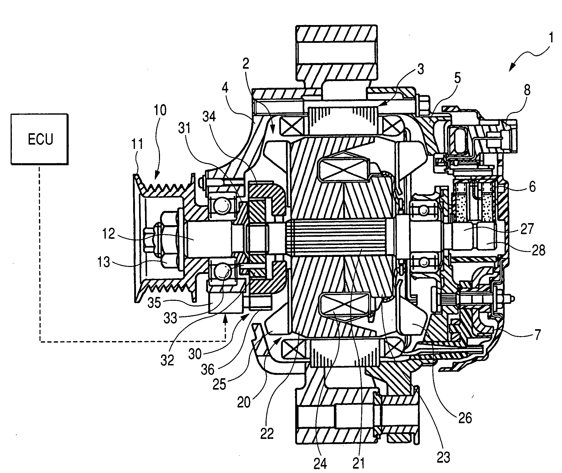
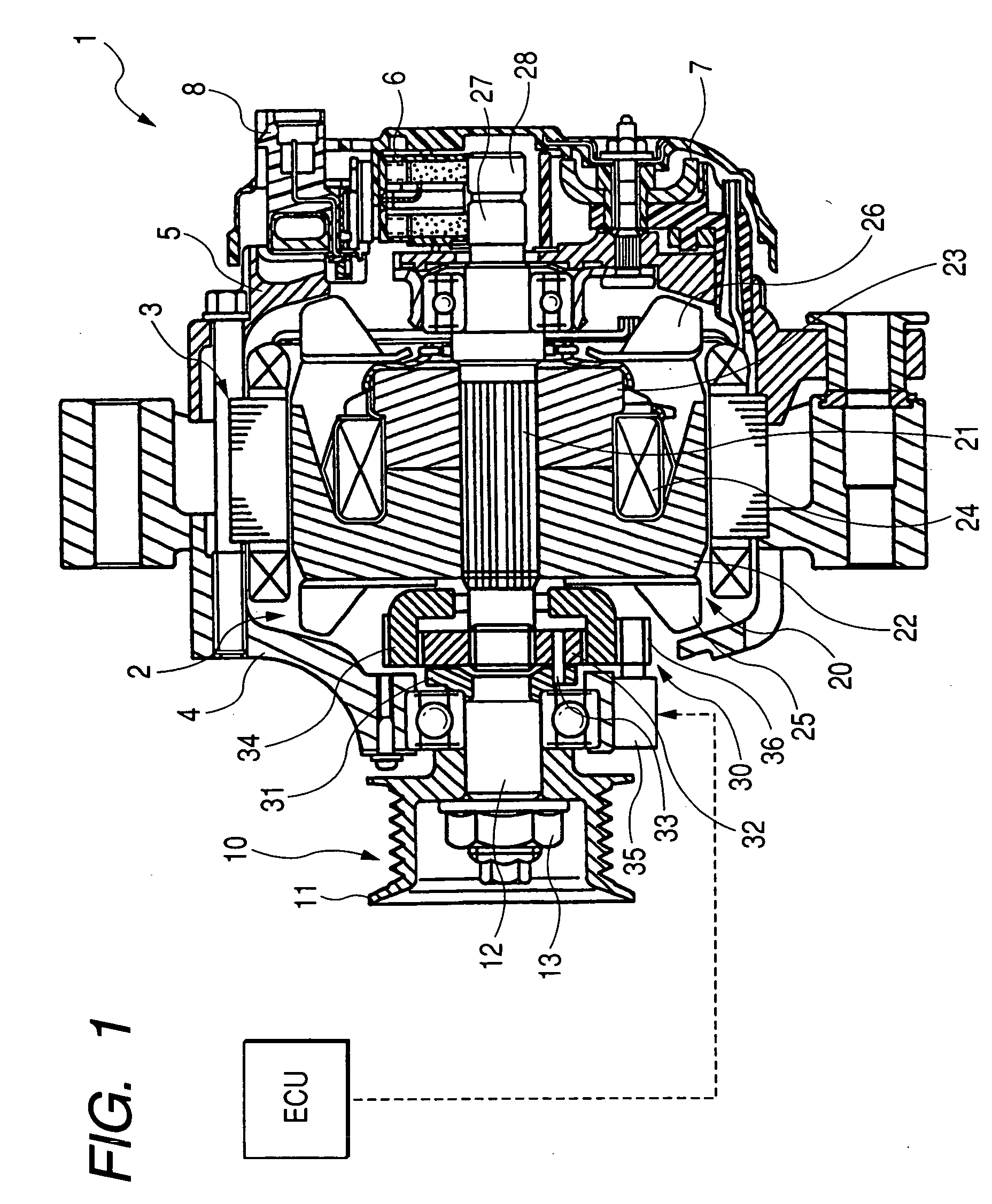
[0031]FIG. 1 is a sectional view of an entire configuration of the vehicle alternator according to the embodiment of the present invention. As shown in FIG. 1, the vehicle alternator 1 has a rotor 2, a stator 3, a housings 4 and 5, a brush device 6, a rectify device 7, and a voltage regulator 8.

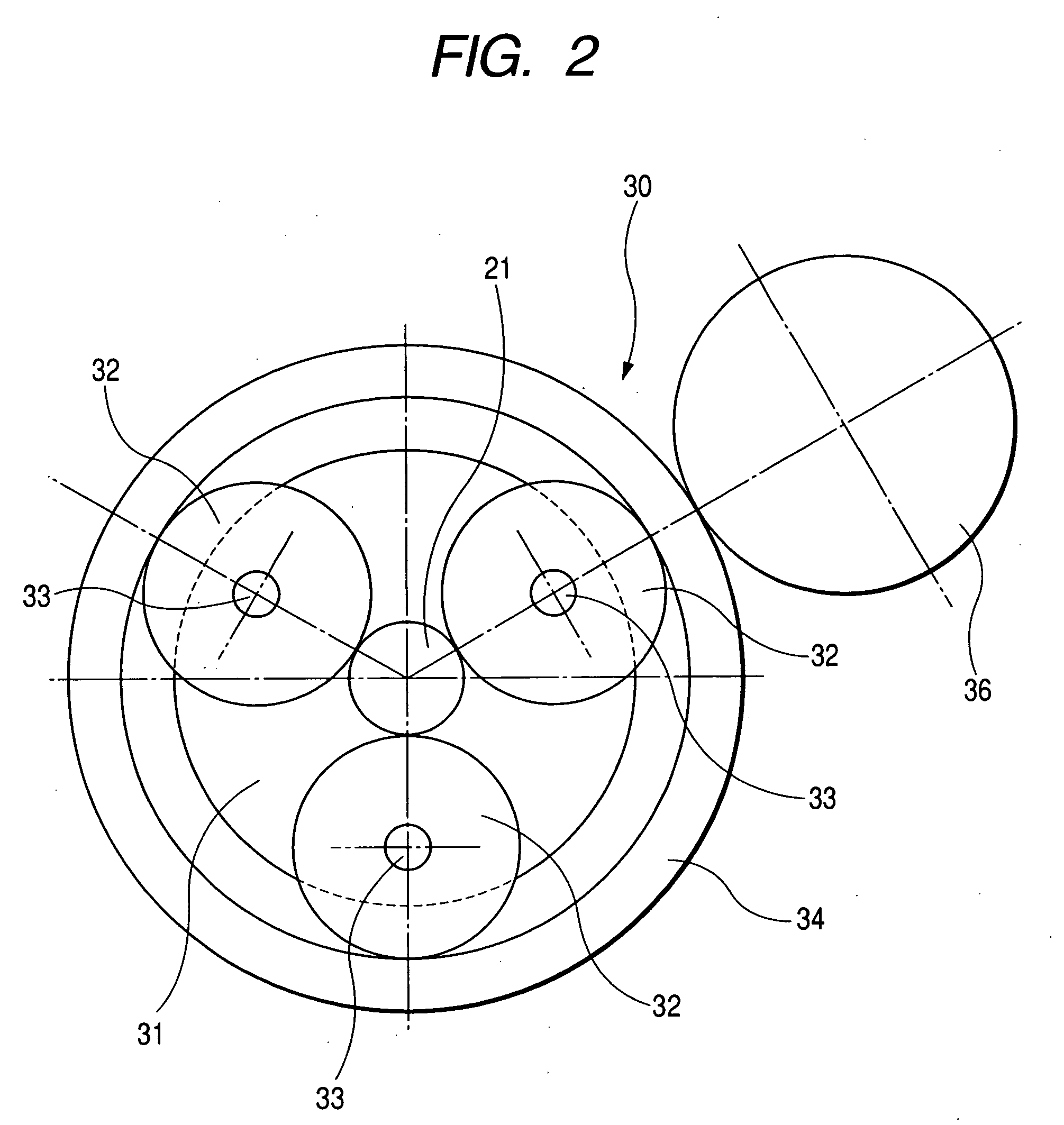
[0032] The rotor 2 has a pulley part 10, a field magnet part 20 separated from the pulley part 10, a rotation speed changing part 30 configured to convert the rotation speed between the pulley part 10 and the field magnet part 20.

[0033] The pulley part 10 has a pulley 11, a pulley rotating shaft 12, and a nut 13. The pulley rotating shaft 12 is configured to transmit to the field magnet part 20 the driving force which is supplied from the engine (such as an internal combustion engine, omitted from the drawings) to the pulley 11 through a drivi...


PUM


Abstract

A vehicle alternator for generating electric power is driven by an engine mounted on a vehicle driven through a driving belt. The alternator has a pulley part joined to and directly receiving a driving force from the engine through the driving belt, a field magnet part located in separation from the pulley part, a rotation speed changing part placed between the pulley part and the field magnet part. The rotation speed changing part converts the number of revolutions between the pulley part and the field magnet part. The rotation speed changing part decreases a speed changing ratio “S” according to increasing of the number of revolutions of the engine, where the speed changing ratio “S” is obtained by dividing the number of revolutions of the field magnet part by the number of revolutions of the pulley part.

Description

CROSS-REFERENCE TO RELATED APPLICATIONS [0001] This application is related to and claims priority from Japanese Patent Application No. 2005-325594 filed on Nov. 10, 2005, the contents of which are hereby incorporated by reference. BACKGROUND OF THE INVENTION [0002] 1. Field of the Invention [0003] The present invention relates to a vehicle alternator or an electric power generator to be mounted on a vehicle such as a passenger car and a truck. [0004] 2. Description of the Related Art [0005] In general, a vehicle alternator is driven by an engine such as an internal combustion engine mounted on a vehicle through a driving belt that joins the vehicle alternator and the engine. Such a vehicle alternator is driven by the rotary force provided from the engine through the driving belt in order to generate an electric power. [0006] A speed increasing ratio of the vehicle alternator is determined based on a ratio between a groove diameter of a crankshaft pulley and a groove diameter of a pu...

Claims


Application Information

Patent Timeline
Patent Type & Authority Applications(United States)
IPC IPC(8): F02N11/04H02K7/10H02P15/00
CPCH02K7/1004H02K7/116
Inventor IHATA, KOUICHIUMEDA, ATSUSHISHIGA, TSUTOMU
Owner DENSO CORP
Why Eureka
Try Eureka