Electronic expansion valve

An electronic expansion valve and valve port technology, applied in the direction of valve devices, valve details, sliding valves, etc., can solve problems such as poor sealing, large internal leakage, and affecting system performance, so as to prevent eccentricity, avoid internal leakage, and ensure reliability effect

Active Publication Date: 2013-12-18
ZHEJIANG SANHUA INTELLIGENT CONTROLS CO LTD
View PDF6 Cites 16 Cited by
  • Summary
  • Abstract
  • Description
  • Claims
  • Application Information

AI Technical Summary

Problems solved by technology

[0012] like figure 2 As shown, when the refrigerant flows in the forward direction, since the side wall of the valve core seat 2' is facing the horizontal interface part 1'2, the circumferential side wall of the valve core seat 2' will be impacted by the high-pressure refrigerant; when the refrigerant pressure appears When fluctuating, it will cause the spool seat 2' to be eccentric, thus causing the spool seat 2' to not seal the main valve port 1'31 tightly, resulting in large internal leakage and affecting the working performance of the system
In addition, the eccentricity of the valve core seat 2' will also cause interference between the valve needle part 3' and the valve core valve port 2'2

Method used


Image

  • Electronic expansion valve
  • Electronic expansion valve
  • Electronic expansion valve

Examples


Embodiment Construction

[0063] The core of the present invention is to provide an electronic expansion valve. When the refrigerant flows forward, the structural design of the electronic expansion valve can avoid the excessive impact of the high-pressure refrigerant on the valve core seat, prevent its eccentricity, and avoid the occurrence of internal leakage. , to ensure the reliability of the system's work.

[0064] In order to enable those skilled in the art to better understand the technical solutions of the present invention, the present invention will be further described in detail below in conjunction with the accompanying drawings and specific embodiments.

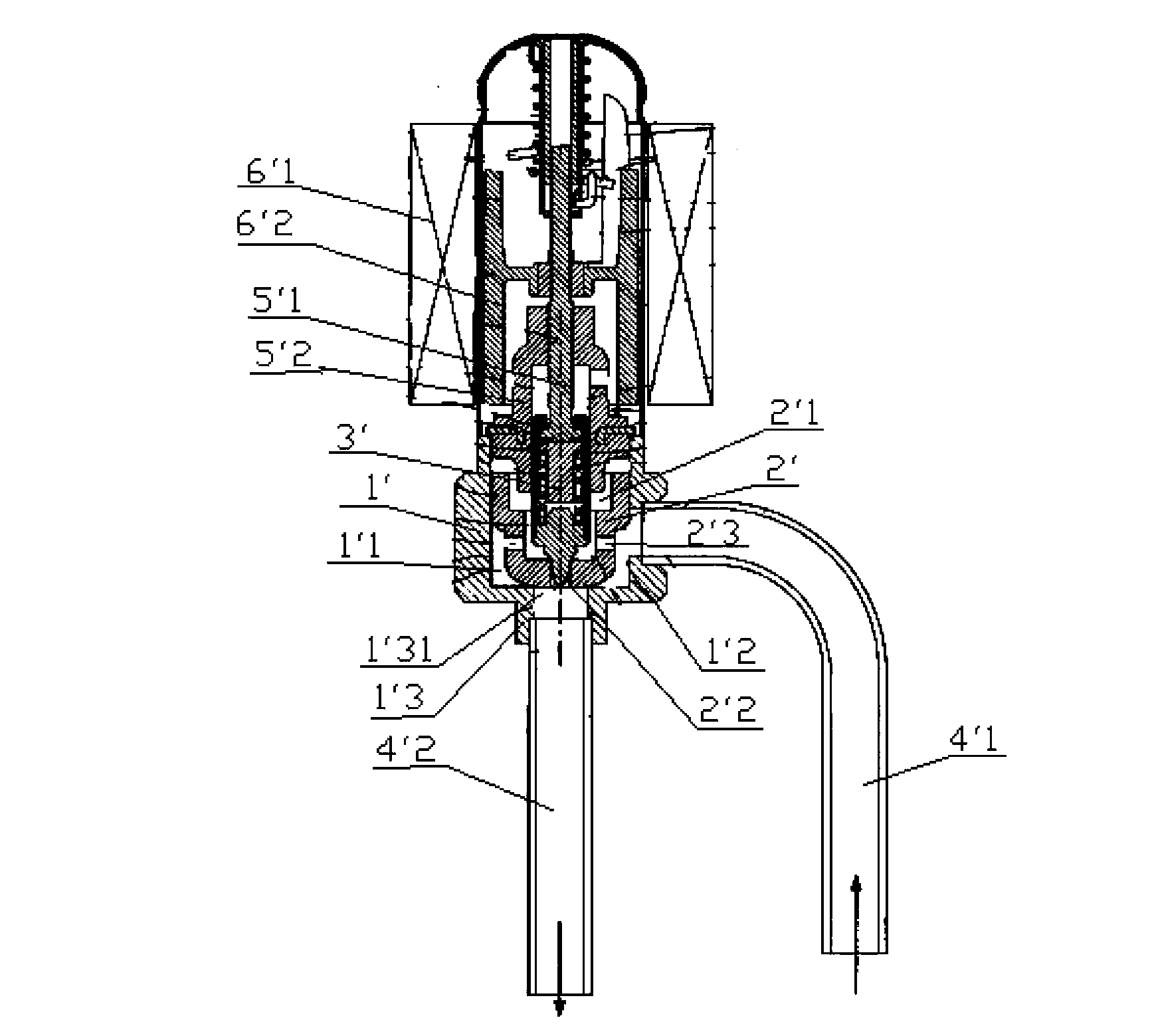
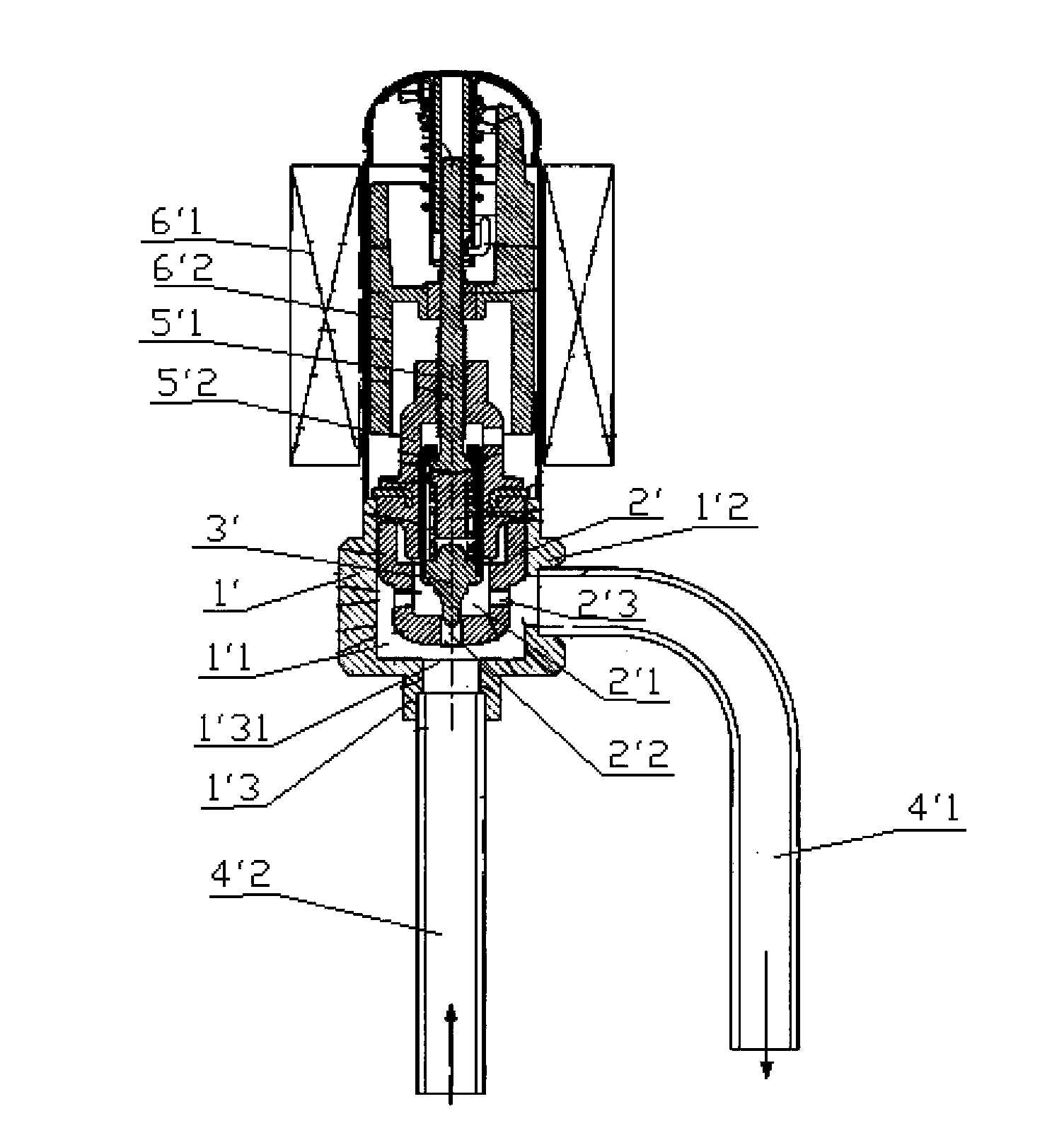
[0065] Please refer to Figure 4 , Figure 5 , Figure 6 and Figure 7 , Figure 4 It is a structural schematic diagram of the electronic expansion valve in the first embodiment of the present invention when the refrigerant flows forward; Figure 5 for Figure 4 Schematic diagram of the structure of the electronic expansion valve in ...


PUM


Abstract

The invention discloses an electronic expansion valve. A sleeve (4) is fixed in a main valve cavity (11), a valve core seat (2) is movably arranged in the sleeve (4) axially, a sleeve runner (41) is arranged on the peripheral side wall of the sleeve (4), and a valve core seat side hole (24) is formed in the peripheral side wall of the valve core seat (2). When a refrigerant is in forward flowing, the valve core seat (2) closes a main valve port (441) to break off communication between the sleeve runner (41) and the valve core seat side hole (24), and the refrigerant flows to a valve core valve port (21) through the sleeve runner (41); when the refrigerant is in backward flowing, the valve core seat (2) is moved upwards to open the main valve port (441) to communicated the valve core seat side hole (24) with the sleeve runner (41); when the refrigerant is in forward flowing, by the structural design of the electronic expansion valve, high-pressure refrigerant can be avoided from causing overlarge impact on the valve core seat, and eccentric phenomena of the valve core seat can be prevented.

Description

technical field [0001] The invention relates to the technical field of fluid control components, in particular to an electronic expansion valve. Background technique [0002] In the air conditioner market, due to the long distance between the indoor unit and the outdoor unit, two electronic expansion valves are used, and the two electronic expansion valves must be connected in parallel with one-way valves to maximize system efficiency. Its system schematic diagram is as follows figure 1 , the working principle is briefly described as follows: [0003] During refrigeration: the high temperature and high pressure gaseous refrigerant coming out of the exhaust pipe of the compressor 7′8 passes through the D connection and E connection of the four-way valve 7′1, the outdoor exchanger 7′2 (condensation and heat release), the first one-way Valve 7'4 (the first electronic expansion valve 7'3 has no regulating effect), the second electronic expansion valve 7'5 (at this time, the se...

Claims


Application Information

Patent Timeline
Patent Type & Authority Applications(China)
IPC IPC(8): F25B41/06F25B41/31
CPCY10T137/88022Y02B30/70F25B41/34F25B41/38F16K3/246F16K47/08
Inventor 不公告发明人
Owner ZHEJIANG SANHUA INTELLIGENT CONTROLS CO LTD
Why Eureka
Try Eureka