
A direction self-judgment odometer

A technology of odometer and direction discrimination

Active Publication Date: 2016-01-20
BEIJING MECHANICAL EQUIP INST
View PDF4 Cites 0 Cited by
  • Summary
  • Abstract
  • Description
  • Claims
  • Application Information

AI Technical Summary

Problems solved by technology

[0003] The purpose of the present invention is to provide a direction self-judging odometer, which solves the problem that the existing odometer can only output the number of pulses, and needs to rely on the gear position signal to judge the moving state of the vehicle forward or backward, and cannot self-judge the rotation direction of the wheel

Method used


Image

  • A direction self-judgment odometer

Examples


Embodiment Construction

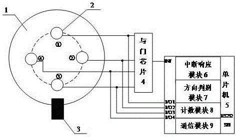
[0011] A direction self-judgment odometer, including: Hall sensor (2) and magnetic steel (3), also includes: AND gate chip (4), single-chip microcomputer (5), interrupt response module (6), direction discrimination module (7 ), counting module (8) and communication module (9). The interrupt response module (6), the direction discrimination module (7), the counting module (8) and the communication module (9) are placed inside the single chip microcomputer (5). The function of the interrupt response module (6) is: to judge the external interruption and communication interruption and call the direction discrimination module (7), the counting module (8) or the communication module (9) for processing; the function of the direction discrimination module (7) is : Discriminate whether the wheel (1) is moving forward or backward; the function of the counting module (8) is: to accumulate and calculate the pulses according to the motion of the wheel (1); the function of the communication...


PUM


Abstract

The invention discloses a speedometer capable of autonomously judging direction. The speedometer comprises Hall sensors (2), magnetic steel (3), an AND gate chip (4), a singlechip (5), an interrupt response module (6), a direction distinguishing module (7), a counting module (8) and a communication module (9), wherein a plurality of Hall sensors (2) are uniformly distributed on the circumference of the axle center of a wheel (1) and generate periodic pulse signals along with the rotation of the wheel (1); the interrupt response module (6) calls the direction distinguishing module (7) to obtain the movement state of the wheel and realizes an autonomous direction judging function by combining the counting module (8) and the communication module (9). The speedometer solves the problem that a vehicle-mounted speedometer cannot provide the movement direction of the carrier autonomously, realizes autonomous judgment on the movement direction of the carrier; furthermore, the speedometer is simple in principle, easy to realize, low in cost, and flexible in working mode, can be applied to a vehicle-mounted navigation and positioning system.

Description

technical field [0001] The invention relates to an odometer, in particular to a direction self-judging odometer. Background technique [0002] In vehicle navigation applications, odometers are often used as the speed sensor of the carrier for speed estimation of the carrier. Existing odometers are composed of multiple magnets and a Hall sensor. Multiple magnets are evenly distributed on the center circumference of the wheel shaft. The Hall sensor is opposite to the circumference of the distributed magnets, and is used to sense the rotation of the wheel and output pulses. number. However, the existing odometer cannot judge the rotation direction of the wheel, and it is difficult to determine whether the motion state of the carrier is moving forward or backward, which brings difficulty to the navigation calculation. In practical applications, it is necessary to rely on the gear position signal of the vehicle to determine whether the vehicle is moving forward or backward, and...

Claims


Application Information

Patent Timeline
Patent Type & Authority Patents(China)
IPC IPC(8): G01C22/02
Inventor 宋高顺于占海
Owner BEIJING MECHANICAL EQUIP INST
Learn More