
Optical crystal encoder of simple structure

An encoder and crystal technology, applied in the encoder field, can solve the problems of unfavorable industrialization, high manufacturing cost, complicated process, etc., and achieve the effect of avoiding waste of resources and saving costs.

Inactive Publication Date: 2013-12-18
郝小妮 +1
View PDF6 Cites 3 Cited by
  • Summary
  • Abstract
  • Description
  • Claims
  • Application Information

AI Technical Summary

Problems solved by technology

However, the existing photoelectric encoders are integrally packaged and molded, which is not only complicated in process, but also high in manufacturing costs, which is not conducive to industrialization, so there is an urgent need for a simple and practical photoelectric encoder

Method used


Image

  • Optical crystal encoder of simple structure
  • Optical crystal encoder of simple structure
  • Optical crystal encoder of simple structure

Examples


Embodiment 1

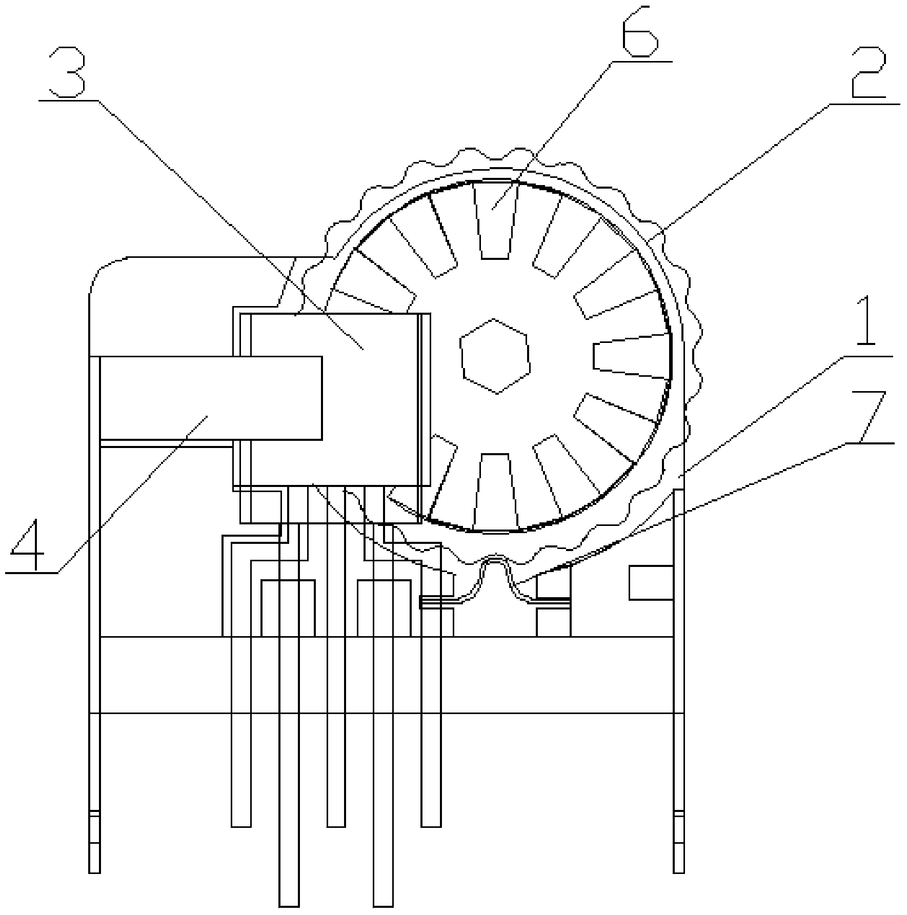
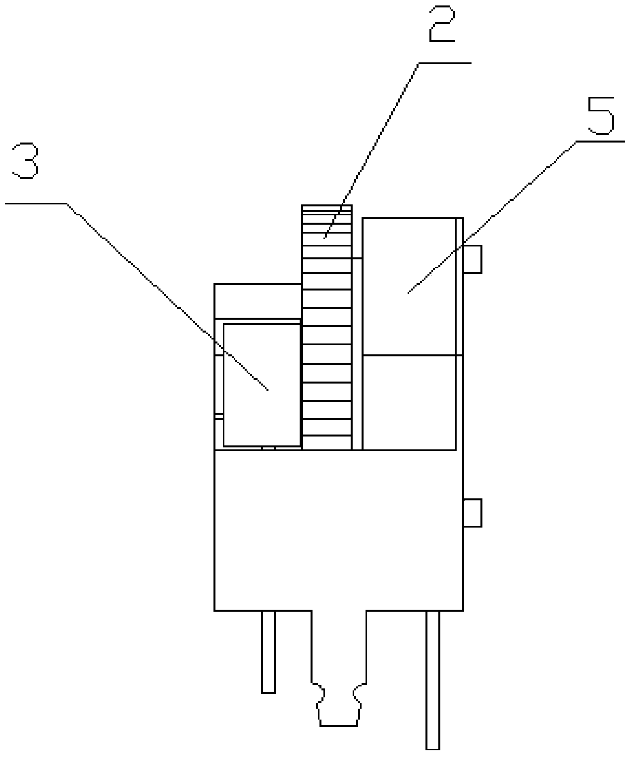
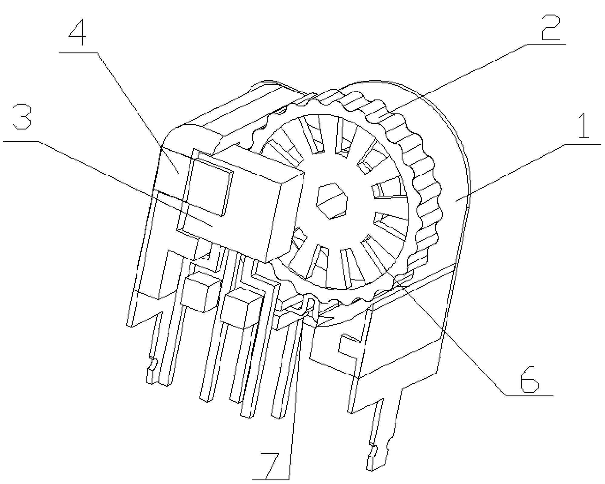
[0023] Such as figure 1 , figure 2 and image 3 As shown, the present embodiment is an optical crystal encoder with a simple structure, including an encoder body 1 and a grid device 2 arranged in the encoder body, and also includes an optical crystal device, which includes an optical crystal emitter device 5 and an optical crystal receiving device 3, the optical crystal emitting device 5 is in the accommodation area of ​​the encoder body 1, and is arranged between the encoder body 1 and the grid device 2, and the optical crystal receiving device 3 is arranged in the grid The surface of the grid device 2, the encoder body 1, the grid device 2 and the optical crystal device are fixed together by the fixing device 4. In this embodiment, the optical crystal receiving device is a vertical optical crystal receiving device, and the two optical crystal receiving devices of the optical crystal The two MOS tubes are vertically arranged, and the vertical optical crystal receiving devi...


PUM


Abstract

The invention discloses an optical crystal encoder of a simple structure. The optical crystal encoder of the simple structure comprises an encoder body and a grating device arranged inside the encoder body, and further comprises an optical crystal device. The optical crystal device comprises an optical crystal emitting device and an optical crystal receiving device. The optical crystal emitting device is arranged in a containing region of the encoder body and between the encoder body and the grating device. The optical crystal receiving device is arranged on the surface of the grating device and the encoder body, the grating device and the optical crystal device are fixed together through fixing devices. The optical crystal encoder of the simple structure overcomes the defects that a common mechanical encoder is short in service life, the service life of the mechanical encoder depends on the service life of a metal rotary disk and the universal mechanical encoder in the market can be used no more than 500 thousand times. However, the optical crystal encoder can be used infinitely theoretically.

Description

technical field [0001] The invention relates to the technical field of encoders, in particular to an optical crystal encoder with a simple structure. Background technique [0002] Existing encoders can generally be classified into mechanical encoders, photoelectric encoders, and mechanical contact encoders. This type of encoder has a limited service life and is not suitable for large-scale industrial production. Photoelectric encoder is a sensor that converts the mechanical geometric displacement on the output shaft into pulse or digital quantity through photoelectric conversion. This is the most widely used sensor at present. The photoelectric encoder is composed of a grating disk and a photoelectric detection device. The grating disk is to open several rectangular holes in equal parts on a circular plate with a certain diameter. Since the photoelectric code disc is coaxial with the motor, when the motor rotates, the grating disc and the motor rotate at the same speed, an...

Claims


Application Information

Patent Timeline
IPC IPC(8): G01D5/347
Inventor 张益乐郝小妮
Owner 郝小妮
Learn More