
Systems and methods for the selection of antennas in aircraft navigation systems

An aircraft, antenna technology, applied to antennas suitable for movable objects, directional diversity systems using radio waves, navigation through velocity/acceleration measurements, etc., to solve problems such as not always being optimally oriented

Inactive Publication Date: 2013-12-18
HONEYWELL INT INC
View PDF0 Cites 11 Cited by
  • Summary
  • Abstract
  • Description
  • Claims
  • Application Information

AI Technical Summary

Problems solved by technology

However, since the ground control station may be located at any location relative to the aircraft, the particular antenna on the aircraft used to receive the ground control station signals will not always be optimally oriented to receive those signals as the aircraft maneuvers

Method used


Image

  • Systems and methods for the selection of antennas in aircraft navigation systems
  • Systems and methods for the selection of antennas in aircraft navigation systems
  • Systems and methods for the selection of antennas in aircraft navigation systems

Examples


example 1

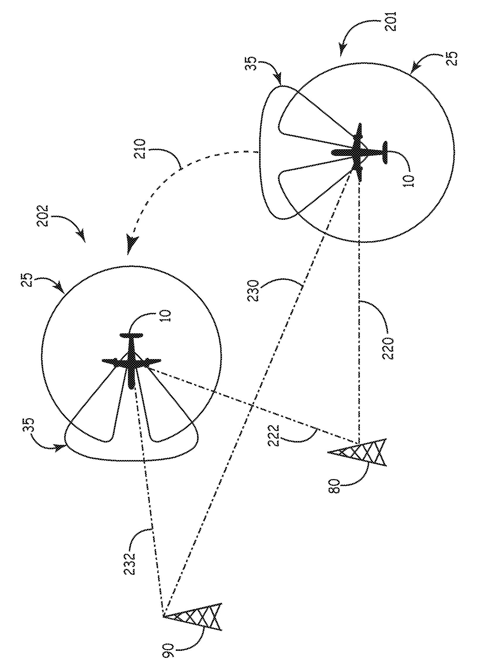
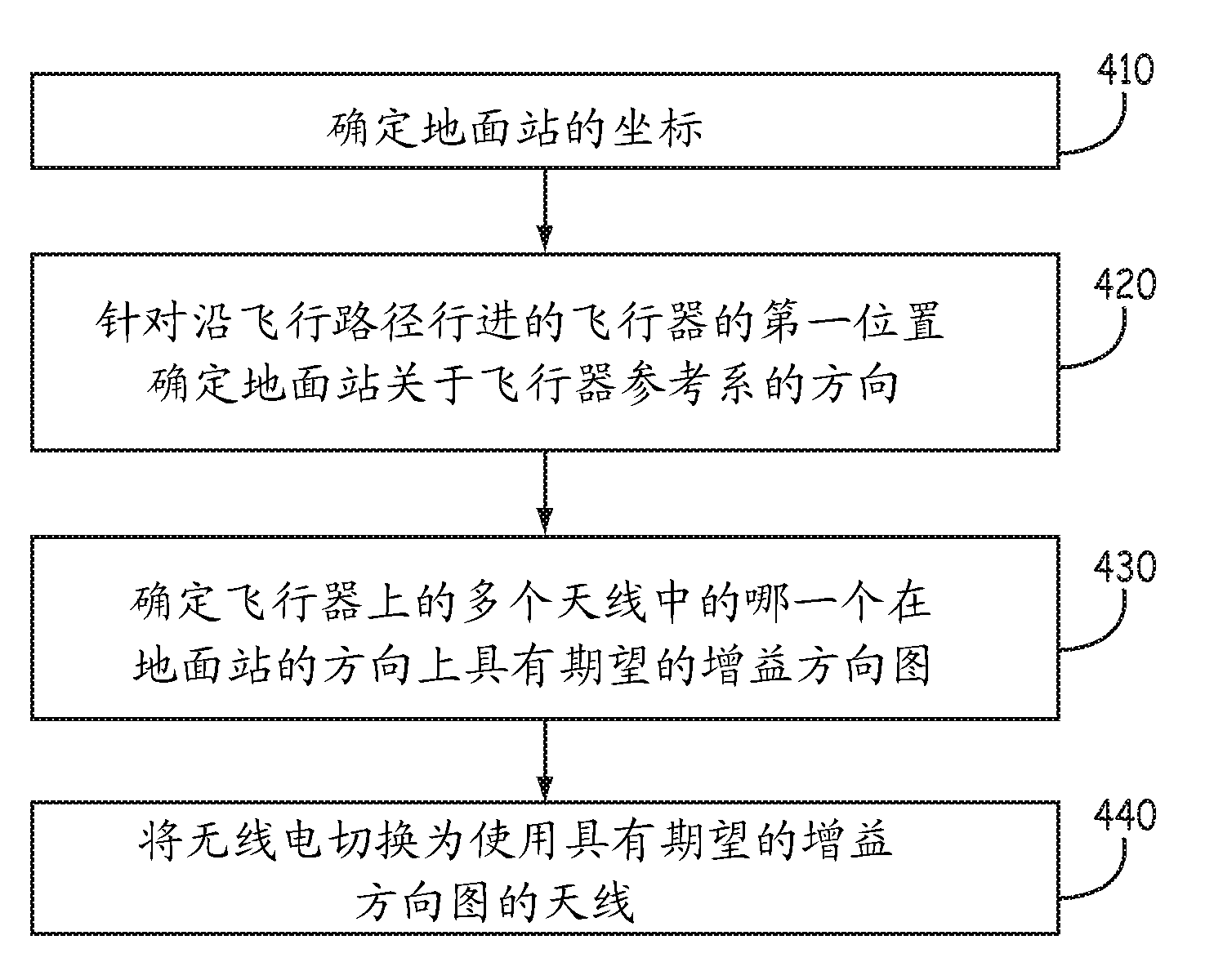
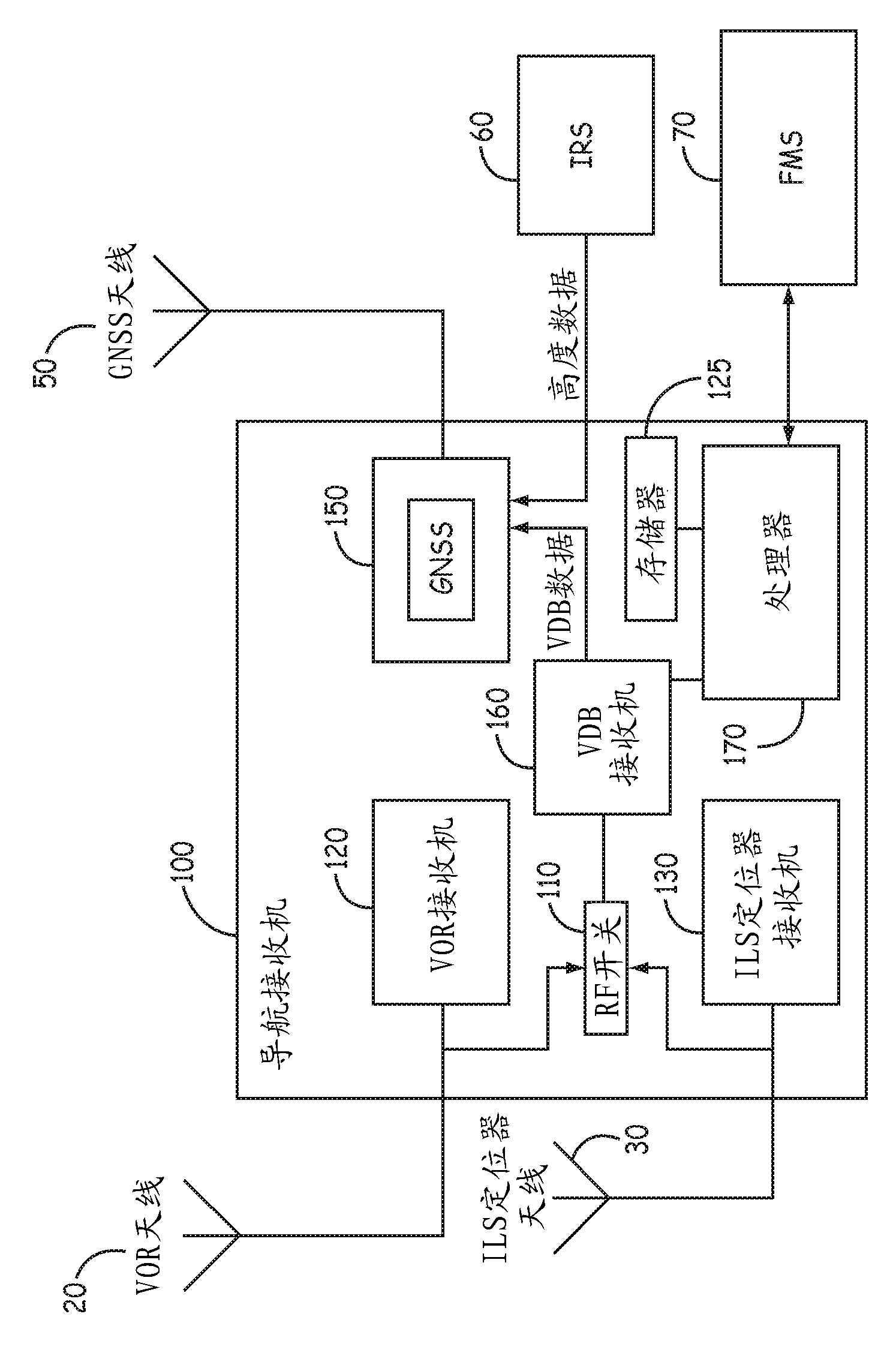
[0048] Example 1 includes a navigation receiver system for an aircraft comprising a first aircraft antenna receiving a transmitter signal from a fixed location ground transmitter and a second aircraft antenna receiving a transmitter signal from the fixed location ground transmitter , wherein the first aircraft antenna has a first gain pattern different from a second gain pattern of the second aircraft antenna; a switch coupled to the first receiver and to the first aircraft antenna and the the second aircraft antenna; and a switch controller coupled to the switch, wherein the switch controller is based on whether the first gain pattern or the second gain pattern is at the fixed location ground transmitter A determination of higher gain is provided in the direction of a first fixed-position ground transmitter in the receiver, operating the switch to electrically couple the first receiver to either the first aircraft antenna or the second aircraft antenna.

example 2

[0049] Example 2 includes the system of example 1, wherein the determination of whether the first gain pattern or the second gain pattern provides higher gain in the direction of the first fixed location ground transmitter is Based on an orientation of the aircraft relative to the first fixed-position ground transmitter as determined at least in part from position information of the aircraft and altitude information of the aircraft.

example 3

[0050] Example 3 includes any of Examples 1-2 above, further comprising: a global navigation satellite system (GNSS) that outputs position information for the aircraft; and an inertial reference system that outputs altitude information for the aircraft.


PUM


Abstract

Systems and methods for the selection of antennas in aircraft navigation systems are provided. In one embodiment, a navigation receiver system for an aircraft comprises: a first aircraft antenna that receives transmitter signals from fixed-location ground transmitters and a second aircraft antenna that receives transmitter signals from the fixed-location ground transmitters, wherein the first aircraft antenna has a first gain pattern that is different from a second gain pattern of the second aircraft antenna; a switch coupled to a first receiver and the first and second aircraft antenna; and a switch controller coupled to the switch. The switch controller operates the switch to electrically couple the first receiver to either the first or second aircraft antenna based on a determination of whether the first gain pattern or the second gain pattern provides higher gain in a direction of a first fixed-location ground transmitter of the fixed-location ground transmitters.

Description

Background technique [0001] Navigational instruments are commonly used to guide aircraft, including unmanned aerial vehicles, especially during more difficult maneuvers such as landings, takeoffs, and emergency situations. These instruments can be used in conjunction with ground-based instrument landing systems (ILS) at ground control stations and runways, and use a combination of radio (RF) signals and possibly high-intensity light beams to help guide the approach and landing of the aircraft. The ground control station transmits RF signals that are received by the aircraft's antenna and receiver electronics connected to the antenna. Ideally, an antenna with an omnidirectional gain pattern is used to receive signals on board the aircraft. [0002] However, the design or location of the antennas may be such that these antennas do not receive signals omnidirectionally. In addition, the conductive fuselage or frame of the aircraft may partially block, distort or reflect electro...

Claims


Application Information

Patent Timeline
Patent Type & Authority Applications(China)
IPC IPC(8): G01S19/15G01S19/39G01C21/16
CPCG01S19/15G01S3/72H01Q1/28H01Q3/24H04B7/0817H04B7/0834H04B7/088H04B7/18506G01S19/25
Inventor J.萨沃伊S.R.斯特隆A.马拉加A.H.卢克
Owner HONEYWELL INT INC
Learn More