

Self-assembly magnetic memorizer and forming method thereof
A memory and magnetic storage technology, applied in the field of ultra-high-density magnetic storage, can solve problems such as loss of stored information, achieve the effect of reducing coupling effects and breaking through physical bottlenecks
- Summary
- Abstract
- Description
- Claims
- Application Information
AI Technical Summary
Benefits of technology
Problems solved by technology
Method used
Image


Examples
Embodiment Construction
[0025] The present invention will be described in further detail below in conjunction with the accompanying drawings and specific embodiments.
[0026] Apparently, the described embodiments are only some of the embodiments of the present invention, but not all of them. Based on the embodiments of the present invention, all other embodiments obtained by persons of ordinary skill in the art without making creative efforts belong to the protection scope of the present invention.
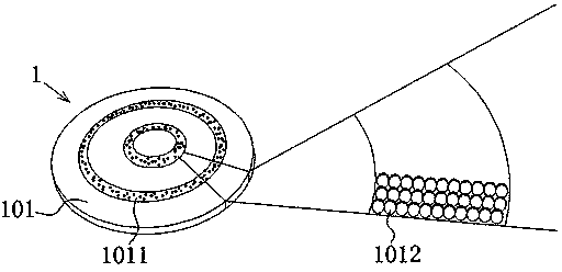
[0027] Figure 1 to Figure 2 A self-assembled magnetic storage memory and a method for forming the same according to an embodiment of the present invention are schematically shown.
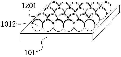
[0028] Such as figure 1 As shown, the self-assembled magnetic storage memory of the present invention includes a memory body 1, and the memory body 1 includes a disk-shaped hard disk substrate 101, and the hard disk substrate 101 is centered on its center of circle, and is provided with several annular track grooves 1011...
PUM
| Property | Measurement | Unit |
|---|---|---|
| Diameter | aaaaa | aaaaa |
| Thickness | aaaaa | aaaaa |
Abstract
Description
Claims
Application Information